Table of Contents
Troubleshooting

Related Manuals for Danfoss 20 Series


Summary of Contents for Danfoss 20 Series
- Page 1 Hydrostatic Pump Repair www.hydrostaticpumprepair.net Phone: 800-361-0028 Email: sales@hydrostatic-transmission.com Service Manual and Repair Instructions Axial Piston Pumps Series 20 powersolutions.danfoss.com...
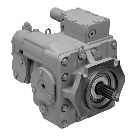
- Page 2 The following manual will provide you with comprehensive instructions for preventative maintenance and recognition of causes of failure of the axial-piston units. Danfoss axial piston variable displacement pumps are of swash plate design with variable flow capability suitable for hydrostatic transmissions with closed loop circuit.
-
Page 3: Table Of Contents
Service Manual and Axial Piston Pumps Series 20 Repair Instructions Contents Model Code Model Code ....................................4 Recommended Tools and Tools for Minor Repairs and Unit Maintenance ......................5 Installation Additional Tools for Complete Stripping of Units ......................5 Measurement Instruments ..............................5 Trouble Shooting, Gauge Installation and Information .................... -
Page 4: Model Code
Service Manual and Axial Piston Pumps Series 20 Repair Instructions Model Code S P V 2 Producer mark Series of product A1 producer specification Pump variable according to construction Association (at present = A1) type 20 Units with working mark Displacement cm 3-letter combination e.g.: = 33.3 [2.03]... -
Page 5: Recommended Tools And Installation
Service Manual and Axial Piston Pumps Series 20 Repair Instructions Recommended Tools and Installation 1 Circlip pliers ∅ 2 to 2.5 mm Tools for Minor Repairs and Unit Maintenance 1 Screw driver 3 mm 1 Screw driver 6 mm 1 Screw driver 9 mm 1 Plastic hammer - small 1 Pointed pliers (can also be slightly bent) 1 Torque key to 14.9 Nm [132 lbf•inch]... -
Page 6: Trouble Shooting, Gauge Installation And Information
Service Manual and Axial Piston Pumps Series 20 Repair Instructions Recommended Tools and Installation Trouble Shooting, Gauge Installation and Information Gauge Information Charge Pressure 60 bar [870 psi] - Gauge 7/16 - 20 UNF O-ring Fitting System pressure 600 bar [8700 psi] - Gauge 7/16 - 20 UNF O-ring Fitting Inlet Vacuum Vacuum gauge... -
Page 7: Start-Up Procedure Preconditions For Trouble-Free Operation
Service Manual and Axial Piston Pumps Series 20 Repair Instructions Start-up procedure Preconditions for Trouble- Cleanliness: Ensure that the pipes, pipe connections and hoses as well as all other components are free Operation completely clean. Ventilation and venting of the oil reservoir via an air filter. Operating fluid: HLP fluid according to DIN 51524, ATF type A SUFFIX A, HD-SAE motor oils, see Fluid Manufacturers, Technical... -
Page 8: First-Time Operation
Service Manual and Axial Piston Pumps Series 20 Repair Instructions Start-up procedure Preconditions for Trouble- The charge pressure measured at the charge pressure gauge connection port of the pump with the free Operation (continued) adjusting lever in the neutral position should be approx. 15 bar [217.6 psi] at a pump input speed n = 1500 min (rpm). - Page 9 Service Manual and Axial Piston Pumps Series 20 Repair Instructions Start-up procedure First-time Operation 11. Stop the prime mover and attach the control linkage to the control handle. Check the fluid level in (continued) the sight glass and fill to proper level if necessary. 12.
-
Page 10: Plumbing Installa Tion (Variable Displacement Pump - Fixed Displacement Motor)
Service Manual and Axial Piston Pumps Series 20 Repair Instructions Start-up procedure Plumbing Installa tion (Variable Displacement Pump – Fixed Displacement Motor) P000 341 System circuit Description HEAT EXCHANGER BYPASS VALVE RESERVOIR VACUUM GAUGE CONTROL HANDLE HEAT EXCHANGER SERVO CONTROL CYLINDER REVERSIBLE VARIABLE DISPLACEMENT PUMP FIXED... -
Page 11: System Maintenance Inlet Filter
(suction) connection. Fill the sample into a closable container that is free of residues. Have the oil examined for serviceability by Danfoss, by Oil Manufacturer or by an appropriate institution. Important: Use only recommended oils! (See Information). -
Page 12: Troubleshooting
Service Manual and Axial Piston Pumps Series 20 Repair Instructions Troubleshooting Inspect high pressure Transmission Operates in Insert charge relief valve Check control one Direction Only check valves (see Series 20 Axial Piston linkage Motors, Service Manual (see page 14) and Repair Instruction) Defective Defective... -
Page 13: Neutral Difficult Or Impossible To Find
Service Manual and Axial Piston Pumps Series 20 Repair Instructions Troubleshooting Neutral Difficult or Check control Inspect control valve Replace Impossible to Find linkage (see page 15) pump Defective Defective Repair Replace control valve or replace (see page 23) System will not Operate in either Direction Check fluid Inspect motor... -
Page 14: Inspection Instructions
Service Manual and Axial Piston Pumps Series 20 Repair Instructions Troubleshooting Inspection Instructions Checking the charge pressure 1. Clean the charge pressure gauge connection on the pump. 2. Pressure gauge (see recommended measuring instruments) to be connected. 3. Set operating speed at 1500 min 4. -
Page 15: Checking The Servo Valve (Control Valve)
Service Manual and Axial Piston Pumps Series 20 Repair Instructions Trouble Shooting Inspection Instructions Checking the servo valve (control valve) (continued) 89, 90 F000 083 F000 082 1. Disconnect the external control linkage from 2. Remove the cap screws (see page 22). the control handle and check for neutral operating with control handle. -
Page 16: Disassembly And Assembly Sectional View
Service Manual and Axial Piston Pumps Series 20 Repair Instructions Disassembly and Assembly Sectional View Axial piston variable displacement pump Swash plate Control handle Servo valve (control valve) Charge pump Input shaft Charge check valve Shaft seal Cylinder block assembly Servo cylinder P005 121E L1003506 •... -
Page 17: Exploded View
Service Manual and Axial Piston Pumps Series 20 Repair Instructions Disassembly and Assembly Exploded View P005 113 Description of parts: 1 Hexagonal screw 28 Piston assembly 65 Hexagonal screw 2 Washer 29 Thrust plate 66 Washer 3 Charge pump assembly 30 Screw 67 Trunnion 4 Gasket charge pump... -
Page 18: Minor Repairs
Service Manual and Axial Piston Pumps Series 20 Repair Instructions Disassembly and Assembly Minor repairs The areas of repair indicated may be serviced, following the procedures in this manual, without invalidating the warranty. Preparation for assembly When using a lifting device, the hooks at the end of the slings, are to be fastened in the rings fitted at the front and rear of the motor body. -
Page 19: Changing The Shaft Seal (Disassembly)
Service Manual and Axial Piston Pumps Series 20 Repair Instructions Disassembly and Assembly Minor repairs Changing the shaft seal (disassembly) (continued) F000 087 Clamp seal puller F000 086 on seal-stationary It is recommended that all shaft seal parts be The seal-stationary is removed next. It is held in replaced. -
Page 20: Changing The Shaft Seal (Assembly)
Service Manual and Axial Piston Pumps Series 20 Repair Instructions Disassembly and Assembly Minor repairs Changing the shaft seal (assembly) (continued) 71 Bronze ring Slide the bronze sealing ring over the shaft and onto the shaft pilot diameter with the O-ring facing the unit. -
Page 21: Changing The Charge Pump And The Charge Check Valves
Service Manual and Axial Piston Pumps Series 20 Repair Instructions Disassembly and Assembly Minor repairs Changing the charge pump and the charge check valves (continued) 1, 2 Socket wrench F000 092 To remove the charge pump, loosen the four (4) cap screws that form a rectangu lar pattern. - Page 22 Service Manual and Axial Piston Pumps Series 20 Repair Instructions Disassembly and Assembly Minor repairs To inspect or replace the charge relief valve, use The removal of the charge check valves requires (continued) a “1“ wrench to remove the hex plug and the the use of a draglink socket.
-
Page 23: Changing The Servo Valve (Control Valve)
Service Manual and Axial Piston Pumps Series 20 Repair Instructions Disassembly and Assembly Minor repairs Changing the servo valve (control valve) (continued) 89, 90 F000 083 F000 046 Thoroughly clean external surfaces with steam or clean solvent and blow dry. Remove the nine (9) cap screws (using 7/16 wrench) and swing control away from housing. -
Page 24: Major Repairs
Service Manual and Axial Piston Pumps Series 20 Repair Instructions Disassembly and Assembly Minor repairs Changing the valve- and bearing plate (disassembly) (continued) 1. Disassembly the charge pump (see pages 21, 7, 8, 9 Socket insert 22). 2. The end-cap screws may not be loosened until the shaft seal has been removed (see page 19). -
Page 25: Changing The Valve- And Bearing Plate (Assembly)
Service Manual and Axial Piston Pumps Series 20 Repair Instructions Disassembly and Assembly counterclockwise clockwise Minor repairs (continued) F000 099 The pump valve plate has two tapered slots running in opposite directions. The valve plate illustrated on the left is for left handed (counter F000 100 clockwise) operation, and the valve plate illustrated on the right is for right handed... - Page 26 Service Manual and Axial Piston Pumps Series 20 Repair Instructions Disassembly and Assembly Minor repairs The valve plate must be positioned with the slot (continued) in the valve plate on the dowel pin of the end cap housing. Torque spanner 7, 8, 9 with extension piece F000 103...
-
Page 27: Changing The Cylinder Block Kit (Disassembly)
Service Manual and Axial Piston Pumps Series 20 Repair Instructions Disassembly and Assembly Minor repairs Changing the cylinder block kit (disassembly) (continued) Cone bearing F000 104 F000 066 After removal of the bearing, slip the spacer out Cone bearing of the bore of the cylinder block. In order to change the cylinder block assembly, the shaft seal must first be removed (page 19) as well as the charge pump (page 21 and 22) and the... -
Page 28: Changing The Cylinder Block Kit (Assembly)
Service Manual and Axial Piston Pumps Series 20 Repair Instructions Disassembly and Assembly Minor repairs (continued) F000 107 F000 106 The cylinder block assembly should be installed Before reassembling the cylinder block assembly, the thrust plate must be withdrawn from the next. -
Page 29: Changing The Swash Plate And Servo Piston (Disassembly)
Service Manual and Axial Piston Pumps Series 20 Repair Instructions Disassembly and Assembly Minor repairs Changing the swash plate and servo piston (disassembly) (continued) In order to be able to replace the swash plate and the servo pistons, the opera tions previously described on the pages 19, 21, 22, 23 and 25 must be carried out. - Page 30 Service Manual and Axial Piston Pumps Series 20 Repair Instructions Disassembly and Assembly Cone bearing F000 114 Take care that the plastic shims are kept together with the respective trunnions. F000 113 Mark the trunnion to facilitate correct re-assembly later, and loosen the three screws on each trunnion.
-
Page 31: Changing The Swash Plate And Servo Piston (Assembly)
Service Manual and Axial Piston Pumps Series 20 Repair Instructions Disassembly and Assembly Major repairs Changing the swash plate and servo piston (assembly) (continued) Swash plate Once several parts have been replaced as connecting link necessary lay the swash plate complete with servo piston, in the pump housing and bring the swash plate connecting link into the correct position. - Page 32 Service Manual and Axial Piston Pumps Series 20 Repair Instructions Disassembly and Assembly Major repairs If adjustment required follow these steps. (continued) a. Back out both servo housings until the spring load is released on the swash plate (check by rocking swash plate).
-
Page 33: Changing The Pump Shaft
Service Manual and Axial Piston Pumps Series 20 Repair Instructions Disassembly and Assembly Torque Major repairs 54, 55, 102 50 Cone bearing spanner (continued) F000 069 Take care that the shaft seal is only fitted after the end cap has been screwed down. If any of those parts are replaced, the shaft end play must be checked: drive shaft - bearings - housing - front cover - end... - Page 34 Service Manual and Axial Piston Pumps Series 20 Repair Instructions Disassembly and Assembly Major repairs Next loosen the front cover screws and remove the front cover together with the gasket. The shaft (continued) with bearing can then be removed. Should the bearings be damaged, the bearing cup in the front cover must also be replaced. Remove the thrust plate and set the pump on the servo housings.
-
Page 35: Installation Torque Values
Service Manual and Axial Piston Pumps Series 20 Repair Instructions Installation Torque Values Installation torque values Nm [lbf•in], series 20 Frame size End cap 36.6 [324] - 50.2 [444] 36.6 [324] - 50.2 [444] 36.6 [324] - 50.2 [444] 61.0 [540] - 73.2 [648] Charge pump 13.6 [120] - 14.9 [132] 13.6 [120] - 14.9 [132]... - Page 36 Phone: +86 21 3418 5200 Danfoss can accept no responsibility for possible errors in catalogues, brochures and other printed material. Danfoss reserves the right to alter its products without notice. This also applies to products already on order provided that such alterations can be made without changes being necessary in specifications already agreed.
Need help?
Do you have a question about the 20 Series and is the answer not in the manual?
Questions and answers