Table of Contents

Related Manuals for Brooks GT1000


Summary of Contents for Brooks GT1000
- Page 1 Installation and Operation Manual X-VA-GT1000-eng Part Number: 541B078AAG GT1000 Series July, 2010 ® Brooks GT1000 Industrial Glass Tube Variable Area Flowmeter Model GT1020 Model GT1024...
- Page 2 Read before proceeding! Brooks Instrument designs, manufactures and tests its products to meet many national and international standards. These products must be properly installed, operated and maintained to ensure they continue to operate within their normal specifications. The following instructions must be adhered to and integrated into your safety program when installing, operating and maintaining Brooks Instrument products.
- Page 3 Installation and Operation Manual X-VA-GT1000-eng Part Number: 541B078AAG GT1000 Series July, 2010 WARNING WARNING GLASS TUBE EXPLOSION HAZARD Protective sleeve must remain over glass tube. GLASS TUBE (Meter sizes 7 - 13 only) EXPLOSION Fasten meter windows securely. Failure to comply could result in serious personal HAZARD injury or property damage.
- Page 4 We appreciate this opportunity to service your flow measurement and control requirements with a Brooks Instrument device. Every day, flow customers all over the world turn to Brooks Instrument for solutions to their gas and liquid low-flow applications. Brooks provides an array of flow measurement and control products for various industries from biopharmaceuticals, oil and gas, fuel cell research and chemicals, to medical devices, analytical instrumentation, semiconductor manufacturing, and more.
-
Page 5: Table Of Contents
Contents Installation and Operation Manual X-VA-GT1000-eng Part Number: 541B078AAG GT1000 Series July, 2010 Paragraph Page Number Number Section 1 Introduction Description ............................1-1 Principle of Operation .......................... 1-1 Specifications ............................1-3 Materials of Construction ........................1-7 Optional Equipment ..........................1-10 Section 2 Installation General .............................. - Page 6 Principle of Operation .......................... 1-1 Cross-Section - GT1000 Flow Tubes with Rib Guides ................ 1-2 GT1000 Floats (Descriptions refer to floats used in the same size tube)) ........... 1-2 GT1000 Family of Meters ........................1-8 GT1000 Family of Meters ........................1-9 Alarm Switch(es) for GT1000 Sizes 7-13 ...................
-
Page 7: Section 1 Introduction
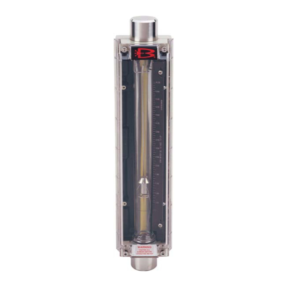
1-1 Description The Brooks ® GT1000 combines ruggedness and simplicity in design to provide a versatile glass tube flowmeter suitable for a wide range of applications. The GT1000 O-ring construction minimizes process downtime by allowing for convenient in-line removal of the glass tube for cleaning and maintenance. -
Page 8: Cross-Section - Gt1000 Flow Tubes With Rib Guides
Type RV- Highest immunity to viscous fluids with medium Type RS - High flow capacity meter capacity. (Most stable) with some immunity to viscous fluids. Type RS Type RV Figure 1-3 GT1000 Floats (Descriptions refer to floats used in the same size tube) -
Page 9: Specifications
Section 1 Introduction Installation and Operation Manual X-VA-GT1000-eng Part Number: 541B078AAG GT1000 Series July, 2010 1-3 Specifications Capacities and Pressure Drop Tables Meter sizes 2-6, rib guided tubes, spherical float. Refer to Table 1-2. Meter sizes 7-13, rib guided tubes, standard float. - Page 10 Section 1 Introduction Installation and Operation Manual X-VA-GT1000-eng Part Number: 541B078AAG GT1000 Series July, 2010 Table 1-1 Pressure Rating & PED Category - Threaded Connections Maximum Operating Pressure (psig / bar) @ Fluid Temperature Listed)* Meter to 200°F to 250°F Size (93°C)
- Page 11 Section 1 Introduction Installation and Operation Manual X-VA-GT1000-eng Part Number: 541B078AAG GT1000 Series July, 2010 Table 1-3 Capacity and Pressure Drop Meter Sizes 2 & 6 WATER AIR* SPHERICAL Flow Rate Pressure Drop V. I. C. Flow Rate Pressure Drop...
- Page 12 Section 1 Introduction Installation and Operation Manual X-VA-GT1000-eng Part Number: 541B078AAG GT1000 Series July, 2010 Table 1-4 Capacities 200mm, 250mm Scale, Rib Guided Tubes, Standard Float Water Air***** Flow Rate Pressure Drop V. I. C.** Flow Rate Pressure Drop REQ.
-
Page 13: Materials Of Construction
Section 1 Introduction Installation and Operation Manual X-VA-GT1000-eng Part Number: 541B078AAG GT1000 Series July, 2010 1-4 Materials of Construction Metering Tube Borosilicate Glass Floats (Figure 1-3) ® Sizes 2 and 6 (spherical): Sapphire, Tantalum, Glass, Carboloy 316 Stainless Steel ®... -
Page 14: Gt1000 Family Of Meters
Section 1 Introduction Installation and Operation Manual X-VA-GT1000-eng Part Number: 541B078AAG GT1000 Series July, 2010 Figure 1-4 GT1000 Family of Meters... -
Page 15: Gt1000 Family Of Meters
Section 1 Introduction Installation and Operation Manual X-VA-GT1000-eng Part Number: 541B078AAG GT1000 Series July, 2010 Figure 1-5 GT1000 Family of Meters Certifications Material certification to DN 3.1 or 2.2 Calibration Certification to NIST and/or NMI Declaration of Compliance 2.1 Oxygen Cleaning... -
Page 16: Optional Equipment
GT1000 Alarm Contacts Meter Sizes 7 to 13 The Brooks reed switch alarm is a normally open, latching switch used in conjunction with the GT1000 glass tube flow meter for signaling high and/or low flow or a deviation from a flow setting. - Page 17 Section 1 Introduction Installation and Operation Manual X-VA-GT1000-eng Part Number: 541B078AAG GT1000 Series July, 2010 Alarm Specifications: Operating Fluid Temperature Limits Reed Switch: Same as meter Inductive: 185°F (85°C) max. Reed Switch Limits - Non-hazardous Locations Maximum Voltage*: 175Vdc, 124Vac...
- Page 18 The alarm points may be adjusted over the entire flowmeter range and be set so that any two contacts may be made to operate simultaneously. For hazardous area applications Brooks can supply an approved namur power supply amplifier/relay unit to obtain an intrinsic safe current circuit.
- Page 19 Valves and flow controllers are available with threaded or flanged connections. Note, solenoid valves should not be used because this type of valve can cause pressure shocks which can damage the glass tube. Figure 1-6 Alarm Switch(es) for GT1000 Sizes 7 - 13 1-13...
-
Page 20: Dimensions And Specs, Intrinsically Safe Switch Isolators
Section 1 Introduction Installation and Operation Manual X-VA-GT1000-eng Part Number: 541B078AAG GT1000 Series July, 2010 Figure 1-7 Dimensions and Specs, Intrinsically Safe Switch Isolators. 1-14... -
Page 21: Alarm Wiring Diagram, Reed Switch & Inductive Alarm With Agency Approved Power Supply/Relay
Section 1 Introduction Installation and Operation Manual X-VA-GT1000-eng Part Number: 541B078AAG GT1000 Series July, 2010 981Y024 Rev A Figure 1-8 Alarm Wiring Diagram, Reed Switch & Inductive Alarm with Agency Approved Power Supply/Relay Isolator and 1-15 Alarm Wiring Diagram, Reed Switch with Customer Supplied Barrier... - Page 22 Section 1 Introduction Installation and Operation Manual X-VA-GT1000-eng Part Number: 541B078AAG GT1000 Series July, 2010 THIS PAGE WAS INTENTIONALLY LEFT BLANK 1-16...
-
Page 23: Section 2 Installation
Section 2 Installation Installation and Operation Manual X-VA-GT1000-eng Part Number: 541B078AAG Model GT1000 Series July, 2010 2-1 General This section contains the procedures for the receipt and installation of the instrument. Do not attempt to start the system until the instrument has been permanently installed. -
Page 24: Return Shipment
Part Number: 541B078AAG Model GT1000 Series July, 2010 2-4 Return Shipment Prior to returning any instrument to the factory visit the Brooks website www.BrooksInstrument for a Return Materials Authorization Number (RMA#), or contact one of the following locations: Brooks Instrument 407 W. -
Page 25: Typical Flowmeter Piping Configuration
Section 2 Installation Installation and Operation Manual X-VA-GT1000-eng Part Number: 541B078AAG Model GT1000 Series July, 2010 HORIZONTAL VERTICAL LINE LINE FLOWMETER FLOWMETER A - Inlet Valve B - Outlet Valve C - Bypass Valve D - Control Valve E - Drain Valve Figure 2-1 Typical Flowmeter Piping Configuration B. - Page 26 Section 2 Installation Installation and Operation Manual X-VA-GT1000-eng Part Number: 541B078AAG Model GT1000 Series July, 2010 ↑ 8" Holes 5/16" Dia. ↓ 1-5/8" ← → Figure 2-2 Drill Template for Front Panel Mounting for Meters Sizes 7, 8, 9 & 10. Consult Factory for...
- Page 27 Installation and Operation Manual X-VA-GT1000-eng Part Number: 541B078AAG Model GT1000 Series July, 2010 7. Slide the metering tube into the upper end fitting. Again be careful not to allow the float to fall out of the metering tube. Insure that the plastic tube retainer is pulled all the way out.
- Page 28 Section 2 Installation Installation and Operation Manual X-VA-GT1000-eng Part Number: 541B078AAG Model GT1000 Series July, 2010 THIS PAGE WAS INTENTIONALLY LEFT BLANK...
-
Page 29: Section 3 Operation
Section 3 Operation Installation and Operation Manual X-VA-GT1000-eng Part Number: 541B078AAG Model GT1000 Series July, 2010 3-1 Pre-Operational Check Prior to initial start-up and each time the flowmeter is reassembled, the scale alignment should be checked. If the reference line on the tube is aligned with the reference line on the scale, the flowmeter is ready for operation. -
Page 30: Typical Flowmeter Piping Configuration
Section 3 Operation Installation and Operation Manual X-VA-GT1000-eng Part Number: 541B078AAG Model GT1000 Series July, 2010 To initiate flow through a flowmeter using bypass piping, refer to Figure 3-1. 1. Close flowmeter inlet valve (A) and outlet valve(B). 2. Fully open bypass valve (C) and slightly open control valve (D). -
Page 31: Overview
Section 4 Maintenance Installation and Operation Manual X-VA-GT1000-eng Part Number: 541B078AAG Model GT1000 Series July, 2010 4-1 Overview... -
Page 32: Cleaning
Section 4 Maintenance Installation and Operation Manual X-VA-GT1000-eng Part Number: 541B078AAG Model GT1000 Series July, 2010 4-2 Cleaning The following procedure may be used for cleaning the tube, float and end fittings. 1. Remove the four screws securing the front window to the meter, then remove the front shield. -
Page 33: Section 5 Parts Assembly
Installation and Operation Manual X-VA-GT1000-eng Part Number: 541B078AAG Model GT1000 Series July, 2010 5-1 General See Figures 5-1 through 5-3 and Table 5-1 for parts assembly drawings and parts list. Ref. MR-1020-Z-038 Figure 5-1 GT1000, Sizes 2 and 6 Parts Assembly Drawing... -
Page 34: Gt1000, Sizes 7-10 Parts Assembly Drawing
Section 5 Parts Assembly Installation and Operation Manual X-VA-GT1000-eng Part Number: 541B078AAG Model GT1000 Series July, 2010 Figure 5-2 GT1000, Sizes 7-10 Parts Assembly Drawing... -
Page 35: Gt1000, Sizes 12 And 13 Parts Assembly Drawing
Section 5 Parts Assembly Installation and Operation Manual X-VA-GT1000-eng Part Number: 541B078AAG Model GT1000 Series July, 2010 Ref. MR-1020-Z-028 Figure 5-3 GT1000, Sizes 12 and 13 Parts Assembly Drawing... - Page 36 Section 5 Parts Assembly Installation and Operation Manual X-VA-GT1000-eng Part Number: 541B078AAG Model GT1000 Series July, 2010 Table 5-1 Parts Assembly Item Identification Item # Description HOUSING TUBE BACKING INLET FTG INSERT OUTLET FTG INSERT O-RING (INSERT TO TUBE) INLET END FITTINGS...
- Page 37 Section A - Essential Instructions Installation and Operation Manual X-VA-GT1000-eng Part Number: 541B078AAG Model GT1000 Series July, 2010 Bulgarian Brooks Instrument Brooks Instrument. Brooks Instrument : (1) . (2) Brooks Instrument (PED) 0,5 bar (g) 25 mm 1" ( (PED).
- Page 38 P ed instalací si p e t te následující instrukce! Spole nost Brooks Instrument konstruuje, vyrábí a testuje tento produkt tak, aby splnil mnoho národních a mezinárodních standard . P ístroje musí být ádn nainstalovány, používány a udržovány tak, aby byl zajišt n jejich nep etržitý provoz v rámci normálních technických specifikací. Musíte dodržovat následující...
- Page 39 Om kvalitet af signalkabler, kabeltilslutninger og koblinger: Brooks tilbyder kabler af højest kvalitet, som er tilpasset CEE kvalificeringens forskrifter. Hvis man vælger at bruge egne kabler, skal man vælge et kabel som har den nødvendige afskærmning for at sikre 100 % mod udefra kommende støj.
- Page 40 Lees ze voordat u verder gaat! Brooks Instrument ontwerpt, produceert en test haar producten zodanig dat ze voldoen aan vele nationale en internationale normen. Deze producten moeten correct worden geïnstalleerd, bediend en onderhouden zodat ze binnen hun normale specificaties blijven werken. De volgende instructies moeten worden toegevoegd aan en geïntegreerd in uw veiligheidsprogramma als u producten van Brooks Instrument installeert, bedient en onderhoudt.
- Page 41 Olulised juhised Enne kasutamist lugege hoolikalt läbi! Brooks Instrument konstrueerib, valmistab ja katsetab oma tooteid selliselt, et need vastaksid paljude erinevate riiklike ja rahvusvaheliste standardite nõuetele. Ainult nõuetekohane paigaldamine, kasutamine ja hooldamine tagab toodete katkematu talitluse tavaspetsifikatsiooni raames. Brooks Instrument'i toodete paigaldamisel, kasutamisel ja hooldamisel tuleb täita alljärgnevaid juhiseid ja integreerida need asjakohasesse ohutusprogrammi.
- Page 42 PED direktiiviä koskevat määräykset löytyvät käyttöoppaan ’’Tekniset tiedot” -luvusta. Käyttöoppaassa kuvatut mittarit ovat 97/23/EC EU-direktiivin mukaisia. Kaikki Brooks Instrumentin virtausmittarit kuuluvat virtausryhmään 1. Laitteet jotka ovat suurempia, kuin 25 mm tai 1 tuuma, ovat PED I, II, III kategorien mukaisia.
- Page 43 Brooks Instrument et que des personnes qualifiées effectuent le remplacement. Les pièces et procédures non autorisées peuvent porter atteinte au fonctionnement du produit et mettre en péril la sécurité de votre procédé. Les remplacements par des pièces d’apparence similaire peuvent entraîner des incendies, des risques électriques ou un mauvais fonctionnement.
- Page 44 Bitte zuerst lesen! Brooks Instrument entwickelt, produziert und testet seine Produkte derart, dass sie viele nationale und internationale Standards erfüllen. Nur bei korrektem Einbau sowie richtiger Bedienung und Wartung dieser Produkte ist ein Betrieb unter Einhaltung der Standardvorgaben sichergestellt. Die folgenden Anweisungen müssen eingehalten werden und in Ihr Sicherheitsprogramm integriert werden, wenn Sie Brooks Produkte installieren, bedienen und warten.
- Page 45 Section A - Essential Instructions Installation and Operation Manual X-VA-GT1000-eng Part Number: 541B078AAG Model GT1000 Series July, 2010 Greek Brooks Instrument Brooks Instrument. ’ Brooks Instrument. : (1) . (2) Brooks Instrument. (PED) 0,5 bar (g) 25 mm (PED). PED.
- Page 46 El ször olvassa el ezeket! A Brooks Instrument olyan módon tervezi, gyártja és teszteli termékeit, hogy azok megfeleljenek számos belföldi és nemzetközi szabványnak. Ezeket a berendezéseket megfelel en kell telepíteni, üzemeltetni és karbantartani ahhoz, hogy mindenképpen a normál m ködési tartományuknak megfelel en üzemelhessenek.
- Page 47 Leggerle subito! La Brooks Instrument progetta, fabbrica e collauda i propri prodotti in maniera tale che siano conformi ai vari standard nazionali ed internazionali. Tali apparecchiature devono essere installate, messe in esercizio e tenute in manutenzione in maniera adeguata affinché operino in conformità alle loro normali specifiche di funzionamento.
- Page 48 P rliecinieties par to, lai pirms instrumenta tehnisk s apkopes b tu likvid ts procesa l nijas spiediens. Ja ir nepieciešams veikt k du da u nomai u, nodrošiniet, lai tiktu izmantotas „Brooks Instrument” nor d t s da as un da u nomai u veiktu kvalific ts person ls. Neat autu da u un proced ru izmantošana var ietekm s ražojuma sniegumu un samazin t procesa droš...
- Page 49 Jei nuot ki n ra, sukurkite sistemoje darbin sl g . Prieš atlikdami prieži ros darbus b tinai pašalinkite sl g proceso linijoje. Jei reikia pakeisti dalis, užtikrinkite, kad kvalifikuoti darbuotojai naudot „Brooks Instrument“...
- Page 50 / lub uszkodzenia sprz tu. Je eli jakie zalecenia w instrukcji obs ugi urz dzenia s niezrozumia e, prosimy o skontaktowanie si z przedstawicielem firmy Brooks Instrument, aby wyja ni problem.
- Page 51 Antes de proceder, leia-as! A Brooks Instrument projecta, fabrica e testa os seus produtos de forma a que os mesmos satisfaçam numerosas normas nacionais e internacionais. Os equipamentos devem ser instalados, explorados e mantidos de maneira adequada, e devem funcionar de acordo com a sua gama de utilização. Durante a instalação, exploração e manutenção dos equipamentos da Brooks Instrument, as instruções seguintes devem ser observadas e integradas no programa de...
- Page 52 În m sura în care indica iile c r ii ma inii nu sunt suficient de l muritoare, lua i leg tura cu reprezentantul Brooks Instrument pentru clarificarea problemei. P stra i toate avertismentele, avizele i instruc iunile livrate odat cu instala ia sau inscrip ionate pe aceasta.
- Page 53 Ke nie je presakovanie, spoje sú tesné, naplni systém na prevádzkový tlak. Pred vykonávaním servisných prác kontrolova , i systém nie je pod tlakom. V prípade, že je potrebná výmena sú iastky, výmenu dielov, ur ených Brooks Instrument musí...
- Page 54 Najprej preberite jih Brooks Instrument tako konstruira, izdeluje in terstira svoje izdelke, da oni ustrezajo številnim doma im in mednarodnim standardom. Te naprave se morajo ustrezno instalirati, koristiti in vzdrževati, da vsekakor delajo ustrezno normalnom podro ju funkcioniranja. Naslednjih navodil se mora držati in potrebno je vgraditi v program varstva pri delu pri instaliranju, koriš...
- Page 55 ¡Léalos primero! El Brooks Instrument proyecta, fabrica y prueba sus productos de manera que éstos respondan a numerosas normas nacionales e internacionales. Dichas instalaciones deben ser emplazadas, operadas y mantenidas adecuadamente, para que puedan marchar de todas formas en conformidad con el alcance normal de funcionamiento.
- Page 56 Läs detta innan du fortsätter ! Brooks Instrument konstruerar, tillverkar och testar sina produkter med syfte att uppfylla alla nationella och internationella standarder. Dessa produkter måste installeras på rätt sätt, handhas och underhållas för att de skall fungera kontinuerligt enligt deras normala specifikation. De följande anvisningarna bör följas och integreras till Ert säkerhetsprogram varje gång när Brooks Instruments produkter installeras, handhas och underhålls.
- Page 57 Installation and Operation Manual X-VA-GT1000-eng Part Number: 541B078AAG Model GT1000 Series July, 2010 THIS PAGE WAS INTENTIONALLY LEFT BLANK...
- Page 58 BROOKS SERVICE AND SUPPORT Brooks is committed to assuring all of our customers receive the ideal flow solution for their application, along with outstanding service and support to back it up. We operate first class repair facilities located around the world to provide rapid response and support.
Need help?
Do you have a question about the GT1000 and is the answer not in the manual?
Questions and answers