
Related Manuals for Brooks 0254


Summary of Contents for Brooks 0254
- Page 1 Installation and Operation Manual X-SE-0254-eng Part Number: 541B129AAG Model 0254 September, 2010 Gas and Liquid Mass Flow Secondary Electronics Model 0254 Table Top Four Channel Secondary Electronics...
- Page 2 Read before proceeding! Brooks Instrument designs, manufactures and tests its products to meet many national and international standards. These products must be properly installed, operated and maintained to ensure they continue to operate within their normal specifications. The following instructions must be adhered to and integrated into your safety program when installing, operating and maintaining Brooks Instrument products.
- Page 3 We appreciate this opportunity to service your flow measurement and control requirements with a Brooks Instrument device. Every day, flow customers all over the world turn to Brooks Instrument for solutions to their gas and liquid low-flow applications. Brooks provides an array of flow measurement and control products for various industries from biopharmaceuticals, oil and gas, fuel cell research and chemicals, to medical devices, analytical instrumentation, semiconductor manufacturing, and more.
- Page 4 Installation and Operation Manual X-SE-0254-eng Part Number: 541B129AAG Model 0254 September, 2010 THIS PAGE WAS INTENTIONALLY LEFT BLANK...
-
Page 5: Table Of Contents
Contents Installation and Operation Manual X-SE-0254-eng Part Number: 541B129AAG Model 0254 September, 2010 Paragraph Page Number Number Section 1 Introduction Description ..........................1-1 1-1-1 Architecture ..........................1-1 1-1-2 Communication .......................... 1-1 1-1-3 Process Controls ........................1-1 1-1-4 Operator Controls and Indicators ....................1-2 1-1-5 Diagnostic Capabilities ....................... - Page 6 Contents Installation and Operation Manual X-SE-0254-eng Part Number: 541B129AAG Model 0254 September, 2010 Paragraph Page Number Number 3-6-2 PV Configuration ........................3-17 3-6-3 Batch Control ..........................3-18 Appendix A Engineering Units Available Engineering Units ....................... A-1 Appendix B Blending Examples Examples 1 through 6 ........................
- Page 7 Warranty, Local Sales/Service Contact Information ..............Back Cover Figures Figure Page Number Number Model 0254 Signal Wiring ......................1-6 Panel Mount Cut-Out Dimensions ..................... 2-4 Table Top Stand Mount Installation .................... 2-5 Power Supply Bracket and Bezel ....................2-8 Rack Installation ......................... 2-9 Home Screen ..........................3-1 User Interface Screen Map ......................
- Page 8 Contents Installation and Operation Manual X-SE-0254-eng Part Number: 541B129AAG Model 0254 September, 2010 THIS PAGE WAS INTENTIONALLY LEFT BLANK...
-
Page 9: Section 1 Introduction
Model 0254 September, 2010 1-1 Description The Brooks Model 0254 is a versatile full-featured measurement and control process instrument, with precision multiple channel capabilities. The architecture supports a wide range of operating capabilities organized to meet the requirements of nearly any high-accuracy measurement and control application. -
Page 10: Operator Controls And Indicators
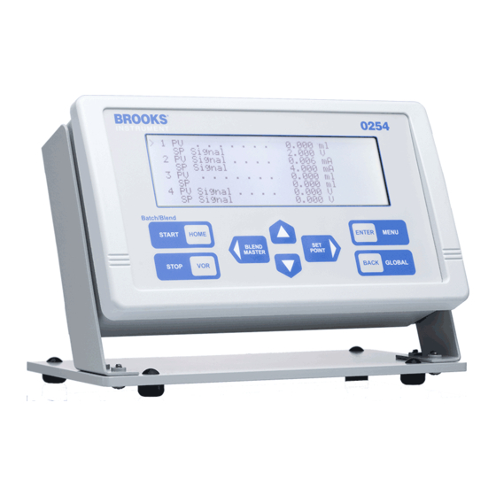
The front panel key pad provides splash proofing and environment protection. The 0254 primary indicator is its large back lit liquid crystal graphic display - visible at a distance even in low light conditions - to view values, support programming operations, and indicate process state information. - Page 11 Section 1 Introduction Installation and Operation Manual X-SE-0254-eng Part Number: 541B129AAG Model 0254 September, 2010 Measurement and Setpoint Accuracy 0.090% of Full Scale Electrical Specifications Input Electrical Characteristics Voltage Input: 0–5, 0-10, 1–5, 2–10 V Volts Input Impedance: 10 K Ohms Current Input: 0–20, 4–20 mA...
- Page 12 Installation and Operation Manual X-SE-0254-eng Part Number: 541B129AAG Model 0254 September, 2010 Power for Model 0254 and Connected Equipment Power Supply Requirements Required: 12–24 Vdc, 2 Amps Additional permitted: –15 Vdc, 1 Amp DC +/- 5% Supply voltage flucuations up to +/- 10% Max current draw per channel : 400 mA Instrument power draw: 0.8 W...
- Page 13 Section 1 Introduction Installation and Operation Manual X-SE-0254-eng Part Number: 541B129AAG Model 0254 September, 2010 Control Service Settings Audio Beep: Selectable audible keystroke, 2 kHz Leading Zero Suppress: Selectable leading zero suppression on display Power Setpoint Clear: Selectable memory retention for Setpoint/VOR...
-
Page 14: Signal Wiring
Rack Mount Kit with 19-in. sub-rack: 19-in. sub-rack included with Rack Mount Kit Retrofit Applications, Model 0152/0154: Rack Mount Kit will adapt the Model 0254 and power supply to the table top enclosure used for the Model 0152/0154 Communications Full communications capability for remote readout setpoint, control,... -
Page 15: Optional Equipment
• User supplied: 12–24 Vdc into 9-pin D connector, 5 A rated 1-4-3 Input/Output Pin-Out Adapters The Model 0254 has four 15-pin female D-channel connectors. The pin configuration is compatible with standard Brooks 0(4)-20 mA cables. An optional pin-out adapter kit with four adapters is available for use with... - Page 16 Section 1 Introduction Installation and Operation Manual X-SE-0254-eng Part Number: 541B129AAG Model 0254 September, 2010 THIS PAGE WAS INTENTIONALLY LEFT BLANK...
-
Page 17: Section 2 Installation
Part Number: 541B129AAG Model 0254 September, 2010 2-1 General This section provides installation instructions for the Model 0254 Gas and Liquid Mass Flow Secondary Electronics device. 2-2 Receipt of Equipment When the instrument is received, the outside packing case should be checked for damage incurred during shipment. -
Page 18: Return Shipment
“as received.” 2-7 Ventilation and Mounting Requirements Because of the low power consumption of the Model 0254, it does not have ventilation requirements. However, the ambient temperature surrounding the Model 0254 should not exeed 122°F (50°C). The optional power supply modules are also ventilation-free and limited to an ambient temperature of 122°F (50°C). -
Page 19: Cable Requirements
360°. The shield should be terminated to earth ground. The optional power supplies available from Brooks are always supplied with a power cord that meets all agency certifications and has a protective conductor for grounding purposes. -
Page 20: Panel Mount Cut-Out Dimensions
Section 2 Installation Installation and Operation Manual X-SE-0254-eng Part Number: 541B129AAG Model 0254 September, 2010 Figure 2-1 Panel Mount Cut-Out Dimensions... -
Page 21: Table Top Stand Assembly Instructions
1. Attach the four rubber mounting feet to the base, as shown in Figure 2-2. 2. Use four of the provided screws to attach the two brackets to the base. 3. Slide the Model 0254 enclosure into the brackets. 4. Use four screws to secure the enclosure to the brackets. CAUTION Do not over-tighten these attachment screws. -
Page 22: Retrofit To Model 0152/0154 Table Top Housing
September, 2010 2-10-3 Retrofit to Model 0152/0154 Table Top Housing It is possible to retrofit the Model 0254 into a table top box that was used for the Model 0152/0154. 1. Slide the flange on the front of the power supply bracket, shown in Figure 2-3 on p. -
Page 23: 19-In. Rack Assembly And Installation Instructions
6. Install the four plastic screw retainers into the bezel, then add the bezel screws. 7. Slide the bezel over the back of the Model 0254 enclosure. Secure the bezel to the enclosure by threading two screws through the holes in the bezel mounting brackets and tightening them. -
Page 24: Power Supply Bracket And Bezel
Section 2 Installation Installation and Operation Manual X-SE-0254-eng Part Number: 541B129AAG Model 0254 September, 2010 Figure 2-3 Power Supply Bracket and Bezel... -
Page 25: Rack Installation
Section 2 Installation Installation and Operation Manual X-SE-0254-eng Part Number: 541B129AAG Model 0254 September, 2010 Figure 2-4 Rack Installation... - Page 26 Section 2 Installation Installation and Operation Manual X-SE-0254-eng Part Number: 541B129AAG Model 0254 September, 2010 THIS PAGE WAS INTENTIONALLY LEFT BLANK 2-10...
-
Page 27: Section 3 Operation
Model 0254 September, 2010 3-1 Home Screen The Model 0254 home screen is the instrument's central information and navigation indicator. The home screen displays following initial power application, and automatically follows the make-model screen banner. It provides an overall view of the instrument's operation. Table 3-1 on p. 3-2 describes the main elements of the home screen. -
Page 28: Operating Controls
Section 3 Operation Installation and Operation Manual X-SE-0254-eng Part Number: 541B129AAG Model 0254 September, 2010 Table 3-1 Display Home Screen Fields Cursor Points to channel even when channel is Off. Channel Numbers 1-4. Description Process value text. Value Numeric process value. -
Page 29: Key Functions
Section 3 Operation Installation and Operation Manual X-SE-0254-eng Part Number: 541B129AAG Model 0254 September, 2010 • Quickly navigate to setpoint or valve override functions • Start and stop control functions • Select a blend control master • Execute the emergency stop function Instructions for the using the above are described in their respective subsections throughout this section. -
Page 30: Navigation
Section 3 Operation Installation and Operation Manual X-SE-0254-eng Part Number: 541B129AAG Model 0254 September, 2010 Present Location System Response All Screens: Selected Item Move cursor left. Home Screen Select channel pointed to by cursor as blend master unless the channel is already the master, in which case the existing master is deselected and no master is chosen. -
Page 31: Display Or Instrument Configuration Screen Selection
Section 3 Operation Installation and Operation Manual X-SE-0254-eng Part Number: 541B129AAG Model 0254 September, 2010 3-3-1 Display or Instrument Configuration Screen Selection Pressing the menu button from the Home screen provides a secondary navigation layer for the operator to specify whether PV-SP Display Configuration or PV-SP Instrument Configuration is desired for a channel. -
Page 32: User Interface Screen Map
Section 3 Operation Installation and Operation Manual X-SE-0254-eng Part Number: 541B129AAG Model 0254 September, 2010 3-3-2 User Interface Screen Map The following diagram showing the screen mapping from the home page to the channel values. Figure 3-2 User Interface Screen Map... -
Page 33: Process Values (Pv) And Setpoints (Sp)
Section 3 Operation Installation and Operation Manual X-SE-0254-eng Part Number: 541B129AAG Model 0254 September, 2010 3-4 Process Values (PV) and Setpoints (SP) This subsection provides a detailed description of the various system map values that are used to set up the instrument's desired operating characteristics. -
Page 34: Pv-Sp Configuration
Section 3 Operation Installation and Operation Manual X-SE-0254-eng Part Number: 541B129AAG Model 0254 September, 2010 PV Signal This value is the measured electrical value being input into the instrument channel. It may be used to provide assistance in system installations, and is used to support instrument calibration. -
Page 35: Value Programming
Section 3 Operation Installation and Operation Manual X-SE-0254-eng Part Number: 541B129AAG Model 0254 September, 2010 3-4-3 Value Programming Program a value by pointing the cursor to its line and pressing the ENTER key. Note a character or string (character string) will be blinking, ready to be edited. - Page 36 Section 3 Operation Installation and Operation Manual X-SE-0254-eng Part Number: 541B129AAG Model 0254 September, 2010 Decimal Point The decimal point for values may be freely selected for none, one, two, or three places. The decimal sets the number of measurement value digits that are to the right of the decimal point.
- Page 37 Section 3 Operation Installation and Operation Manual X-SE-0254-eng Part Number: 541B129AAG Model 0254 September, 2010 Batching Batching is a discontinuous control process that delivers the quantity set in the SP Batch. This process is started using either the keypad or a serial communication command.
-
Page 38: Global Settings
Section 3 Operation Installation and Operation Manual X-SE-0254-eng Part Number: 541B129AAG Model 0254 September, 2010 3-5 Global Settings Global settings are the various system wide variables used to set up and review the overall operating characteristics that establish how the entire instrument will perform. -
Page 39: Global System Power
Section 3 Operation Installation and Operation Manual X-SE-0254-eng Part Number: 541B129AAG Model 0254 September, 2010 Check Sum This value is the hexadecimal double word sum of the instruction read-only memory used for factory quality assurance, and is only for viewing. -
Page 40: Global Control Services
Section 3 Operation Installation and Operation Manual X-SE-0254-eng Part Number: 541B129AAG Model 0254 September, 2010 3-5-3 Global Control Services To enter the Control Services screen, point the cursor to Control Services on the Global Settings screen and press the ENTER key. -
Page 41: Global Communication
Section 3 Operation Installation and Operation Manual X-SE-0254-eng Part Number: 541B129AAG Model 0254 September, 2010 3-5-4 Global Communication To enter the Communications service screen, point the cursor to Communications on the Global Settings screen and press the ENTER key. The Network Addr (address) is shown on the service screen. The Network Address is a unique identification for the instrument operating in a network environment. - Page 42 Section 3 Operation Installation and Operation Manual X-SE-0254-eng Part Number: 541B129AAG Model 0254 September, 2010 4. Scroll down to the SP Rate option and select the flow rate setpoint that is desired. This control type causes an SP Rate signal programmed by the operator to be output to a controller.
-
Page 43: Pv Configuration
Section 3 Operation Installation and Operation Manual X-SE-0254-eng Part Number: 541B129AAG Model 0254 September, 2010 Terminate Rate Control When the channel SP Rate is set to zero, the process is off. To set setpoint to zero, use the Setpoint hot key or the Instrument Configuration screen. -
Page 44: Batch Control
Section 3 Operation Installation and Operation Manual X-SE-0254-eng Part Number: 541B129AAG Model 0254 September, 2010 3-6-3 Batch Control Batch processing is a non-continuous process that is started, conducted, and terminated when a desired quantity has completed delivery. You can stop batch delivery at any time prior to completion. - Page 45 Section 3 Operation Installation and Operation Manual X-SE-0254-eng Part Number: 541B129AAG Model 0254 September, 2010 Terminate Batches Batching for each channel set for batch will automatically terminate when each batch channel PV Total has reached or exceeded its programmed SP Batch setpoint.
- Page 46 Section 3 Operation Installation and Operation Manual X-SE-0254-eng Part Number: 541B129AAG Model 0254 September, 2010 3-6-4-1 Blend Control Setup Program the above values for master and slave channels desired to perform blending. Select Blend Master From the home screen, point to a channel desired to be the master and press the master blend key.
- Page 47 Section 3 Operation Installation and Operation Manual X-SE-0254-eng Part Number: 541B129AAG Model 0254 September, 2010 Slave Channels Setup Navigate to each desired slave channel and set each SP Function to Blend, then set the desired SP Blend rate percentage referenced to the master channels actual delivery rate.
- Page 48 Section 3 Operation Installation and Operation Manual X-SE-0254-eng Part Number: 541B129AAG Model 0254 September, 2010 3-6-4-3 Terminate Blend In-Process Once blending has started, it will continue unless manually terminated. To terminate blending: 1. Return to the Home screen, if not already there, and press the STOP key.
- Page 49 Section 3 Operation Installation and Operation Manual X-SE-0254-eng Part Number: 541B129AAG Model 0254 September, 2010 Once activated, the SP VOR function mode is shown on the appropriate channel display to indicate which VOR function mode is active. The setting of the SP VOR Valve override function is memorized. After power down and power up, the memorized SP VOR function mode will remain in the previous mode until it is changed by the operator.
- Page 50 Section 3 Operation Installation and Operation Manual X-SE-0254-eng Part Number: 541B129AAG Model 0254 September, 2010 5. Once selected, return to the Home screen. The Totalizer value will now be displayed on the channel PV line. The accumulated quantity value displayed is updated in real time as the value changes.
- Page 51 Model 0254 September, 2010 3-1 Home Screen The Model 0254 home screen is the instrument's central information and navigation indicator. The home screen displays following initial power application, and automatically follows the make-model screen banner. It provides an overall view of the instrument's operation. Table 3-1 on p. 3-2 describes the main elements of the home screen.
- Page 52 Section 3 Operation Installation and Operation Manual X-SE-0254-eng Part Number: 541B129AAG Model 0254 September, 2010 Table 3-1 Display Home Screen Fields Cursor Points to channel even when channel is Off. Channel Numbers 1-4. Description Process value text. Value Numeric process value.
- Page 53 Section 3 Operation Installation and Operation Manual X-SE-0254-eng Part Number: 541B129AAG Model 0254 September, 2010 • Quickly navigate to setpoint or valve override functions • Start and stop control functions • Select a blend control master • Execute the emergency stop function Instructions for the using the above are described in their respective subsections throughout this section.
- Page 54 Section 3 Operation Installation and Operation Manual X-SE-0254-eng Part Number: 541B129AAG Model 0254 September, 2010 Present Location System Response All Screens: Selected Item Move cursor left. Home Screen Select channel pointed to by cursor as blend master unless the channel is already the master, in which case the existing master is deselected and no master is chosen.
- Page 55 Section 3 Operation Installation and Operation Manual X-SE-0254-eng Part Number: 541B129AAG Model 0254 September, 2010 3-3-1 Display or Instrument Configuration Screen Selection Pressing the menu button from the Home screen provides a secondary navigation layer for the operator to specify whether PV-SP Display Configuration or PV-SP Instrument Configuration is desired for a channel.
- Page 56 Section 3 Operation Installation and Operation Manual X-SE-0254-eng Part Number: 541B129AAG Model 0254 September, 2010 3-3-2 User Interface Screen Map The following diagram showing the screen mapping from the home page to the channel values. Figure 3-2 User Interface Screen Map...
- Page 57 Section 3 Operation Installation and Operation Manual X-SE-0254-eng Part Number: 541B129AAG Model 0254 September, 2010 3-4 Process Values (PV) and Setpoints (SP) This subsection provides a detailed description of the various system map values that are used to set up the instrument's desired operating characteristics.
- Page 58 Section 3 Operation Installation and Operation Manual X-SE-0254-eng Part Number: 541B129AAG Model 0254 September, 2010 PV Signal This value is the measured electrical value being input into the instrument channel. It may be used to provide assistance in system installations, and is used to support instrument calibration.
- Page 59 Section 3 Operation Installation and Operation Manual X-SE-0254-eng Part Number: 541B129AAG Model 0254 September, 2010 3-4-3 Value Programming Program a value by pointing the cursor to its line and pressing the ENTER key. Note a character or string (character string) will be blinking, ready to be edited.
- Page 60 Section 3 Operation Installation and Operation Manual X-SE-0254-eng Part Number: 541B129AAG Model 0254 September, 2010 Decimal Point The decimal point for values may be freely selected for none, one, two, or three places. The decimal sets the number of measurement value digits that are to the right of the decimal point.
- Page 61 Section 3 Operation Installation and Operation Manual X-SE-0254-eng Part Number: 541B129AAG Model 0254 September, 2010 Batching Batching is a discontinuous control process that delivers the quantity set in the SP Batch. This process is started using either the keypad or a serial communication command.
- Page 62 Section 3 Operation Installation and Operation Manual X-SE-0254-eng Part Number: 541B129AAG Model 0254 September, 2010 3-5 Global Settings Global settings are the various system wide variables used to set up and review the overall operating characteristics that establish how the entire instrument will perform.
- Page 63 Section 3 Operation Installation and Operation Manual X-SE-0254-eng Part Number: 541B129AAG Model 0254 September, 2010 Check Sum This value is the hexadecimal double word sum of the instruction read-only memory used for factory quality assurance, and is only for viewing.
- Page 64 Section 3 Operation Installation and Operation Manual X-SE-0254-eng Part Number: 541B129AAG Model 0254 September, 2010 3-5-3 Global Control Services To enter the Control Services screen, point the cursor to Control Services on the Global Settings screen and press the ENTER key.
- Page 65 Section 3 Operation Installation and Operation Manual X-SE-0254-eng Part Number: 541B129AAG Model 0254 September, 2010 3-5-4 Global Communication To enter the Communications service screen, point the cursor to Communications on the Global Settings screen and press the ENTER key. The Network Addr (address) is shown on the service screen. The Network Address is a unique identification for the instrument operating in a network environment.
- Page 66 Section 3 Operation Installation and Operation Manual X-SE-0254-eng Part Number: 541B129AAG Model 0254 September, 2010 4. Scroll down to the SP Rate option and select the flow rate setpoint that is desired. This control type causes an SP Rate signal programmed by the operator to be output to a controller.
- Page 67 Section 3 Operation Installation and Operation Manual X-SE-0254-eng Part Number: 541B129AAG Model 0254 September, 2010 Terminate Rate Control When the channel SP Rate is set to zero, the process is off. To set setpoint to zero, use the Setpoint hot key or the Instrument Configuration screen.
- Page 68 Section 3 Operation Installation and Operation Manual X-SE-0254-eng Part Number: 541B129AAG Model 0254 September, 2010 3-6-3 Batch Control Batch processing is a non-continuous process that is started, conducted, and terminated when a desired quantity has completed delivery. You can stop batch delivery at any time prior to completion.
- Page 69 Section 3 Operation Installation and Operation Manual X-SE-0254-eng Part Number: 541B129AAG Model 0254 September, 2010 Terminate Batches Batching for each channel set for batch will automatically terminate when each batch channel PV Total has reached or exceeded its programmed SP Batch setpoint.
- Page 70 Section 3 Operation Installation and Operation Manual X-SE-0254-eng Part Number: 541B129AAG Model 0254 September, 2010 3-6-4-1 Blend Control Setup Program the above values for master and slave channels desired to perform blending. Select Blend Master From the home screen, point to a channel desired to be the master and press the master blend key.
- Page 71 Section 3 Operation Installation and Operation Manual X-SE-0254-eng Part Number: 541B129AAG Model 0254 September, 2010 Slave Channels Setup Navigate to each desired slave channel and set each SP Function to Blend, then set the desired SP Blend rate percentage referenced to the master channels actual delivery rate.
- Page 72 Section 3 Operation Installation and Operation Manual X-SE-0254-eng Part Number: 541B129AAG Model 0254 September, 2010 3-6-4-3 Terminate Blend In-Process Once blending has started, it will continue unless manually terminated. To terminate blending: 1. Return to the Home screen, if not already there, and press the STOP key.
- Page 73 Section 3 Operation Installation and Operation Manual X-SE-0254-eng Part Number: 541B129AAG Model 0254 September, 2010 Once activated, the SP VOR function mode is shown on the appropriate channel display to indicate which VOR function mode is active. The setting of the SP VOR Valve override function is memorized. After power down and power up, the memorized SP VOR function mode will remain in the previous mode until it is changed by the operator.
- Page 74 Section 3 Operation Installation and Operation Manual X-SE-0254-eng Part Number: 541B129AAG Model 0254 September, 2010 5. Once selected, return to the Home screen. The Totalizer value will now be displayed on the channel PV line. The accumulated quantity value displayed is updated in real time as the value changes.
-
Page 75: Appendix A Engineering Units
Appendix A Engineering Units Installation and Operation Manual X-SE-0254-eng Part Number: 541B129AAG Model 0254 September, 2010 A-1 Available Engineering Units cm^3 cm^3s cm^3n m^3s m^3n ft^3 ft^3s ft^3n mbar Torr Volt g/cc lb/in^3 lb/ft^3 lb/gal kg/m^3 g/ml kg/l Note: “. ^3” means cubic “ . - Page 76 Appendix A Engineering Units Installation and Operation Manual X-SE-0254-eng Part Number: 541B129AAG Model 0254 September, 2010 THIS PAGE WAS INTENTIONALLY LEFT BLANK...
-
Page 77: Appendix B Blending Examples
Appendix B Blending Examples Installation and Operation Manual X-SE-0254-eng Part Number: 541B129AAG Model 0254 September, 2010 B-1 Blending Examples Example 1: Example 4: Master channel flow is 80 l/min Master channel flow is 100% Slave channel flow has to be 0.8 l/min... - Page 78 Appendix B Blending Examples Installation and Operation Manual X-SE-0254-eng Part Number: 541B129AAG Model 0254 September, 2010 THIS PAGE WAS INTENTIONALLY LEFT BLANK...
-
Page 79: Appendix C Serial Communications Protocol
The platform supports various communication facilities. Channels and Ports The Model 0254 is comprised of pairs of ports, each of which has an input and output to form a channel, with four channels total. Channel and port numbering... -
Page 80: C-2-2 Hyperterminal Setup
Within the windows operating system a software application is available, called Hyperterminal, which can be used to setup a serial connection to the 0254 Read Out. This software application is available in the following shortcut menu “Start->All Programs->Accessories->Communications- >Hyperterminal”. This shortcut will put up the screen shown below.”... - Page 81 Section C Serial Communications Protocol Installation and Operation Manual X-SE-0254-eng Part Number: 541B129AAG Model 0254 September, 2010 In the 'Port Settings' screen enter the values as shown in the picture below and click the 'OK' button. Open the 'File->Properties' pull down menu and click the ASCII Setup' button and configure the settings as shown below.
- Page 82 Section C Serial Communications Protocol Installation and Operation Manual X-SE-0254-eng Part Number: 541B129AAG Model 0254 September, 2010...
-
Page 83: Serial Command Organization
ASCII hexadecimal checksum character. Checksum Two ASCII hexadecimal characters created for a Model 0254 negated sum of all characters available in the Information Frame, which is used by a host computer to check a message packet’s validity. -
Page 84: C-3-2 Command Addressing
September, 2010 C-3-2 Command Addressing Each Model 0254 unit is assigned a unique 5-digit address, from 0 to 65535, which must be pre-programmed in the instrument prior to deployment in a networked system. The ports that comprise a channel are designated with an appended [.x} or [.xx] sub-address. -
Page 85: Command Operation
HOST SEND AZM<cr> Non-network AZ[yyyyy]M<cr> Network RESPONSE <cr><lf><lf><lf><lf><lf><lf><lf><lf><lf><lf><lf><lf><lf><lf><lf><lf> Brooks Instruments COMMANDS - Model 0254 V01.03.21 FD00 <cr><lf><lf> [M] Command Select Menu<cr><lf> [V] Display Port Values<cr><lf> [K] Send Measured<cr><lf> [I] Product Identify<cr><lf> [P] Program New Values<cr><lf> [Z] Clear Measured Values<cr><lf> [F] Batch Control Service<cr><lf>... -
Page 86: C-4-1-3 View Programmed Channel Port Values
Section C Serial Communications Protocol Installation and Operation Manual X-SE-0254-eng Part Number: 541B129AAG Model 0254 September, 2010 C-4-1-3 View Programmed Channel Port Values This command enables the operator to review all present programmed channel port values. HOST SEND AZ.xxV<cr> Non-network xx=port number (1-8) AZ[yyyyy.xx]V<cr>... -
Page 87: C-4-1-5 Message Serial Character Pacing Controls
Section C Serial Communications Protocol Installation and Operation Manual X-SE-0254-eng Part Number: 541B129AAG Model 0254 September, 2010 C-4-1-5 Message Serial Character Pacing Controls These commands provide for the terminal or host to suspend character sending or to re-enable the sending to continue. This facility is particularly useful when the instrument sends large data amounts, such as logged information. -
Page 88: C-4-1-6 Serial Message Error Control
Section C Serial Communications Protocol Installation and Operation Manual X-SE-0254-eng Part Number: 541B129AAG Model 0254 September, 2010 C-4-1-6 Serial Message Error Control Commands provide for error control of information packets sent by the instrument. This is particularly useful when transferring information over wide area networks, and causes the instrument to continue to send the next packet or to resend a previous sent packet. -
Page 89: C-4-2 Channel Input Port Commands
AZ,00909.01,2,xxxxxxxx.xx,00162871.43,-0000003.27,xxxxxxx.xx,xxxxx,X,X,X,X,X,<sum><cr><lf> Explanation of response values above Parameter Value in Description Number Example response pre delimiter 00909 network address of 0254 Read Out device port number (input port channel 1) response type xxxxxxxx.xx Non resettable totalizer value 00162871.43 T otalizer value 0000003.27... -
Page 90: C-4-2-2 Send Channel Input Port Programmed Values
Section C Serial Communications Protocol Installation and Operation Manual X-SE-0254-eng Part Number: 541B129AAG Model 0254 September, 2010 C-4-2-2 Send Channel Input Port Programmed Values This command enables a terminal operator or host to acquire the present state of input port programmed values. Valid input port numbers (xx) are [1, 3, 5, 7]. -
Page 91: C-4-2-3 Program Channel Input Port Values
Section C Serial Communications Protocol Installation and Operation Manual X-SE-0254-eng Part Number: 541B129AAG Model 0254 September, 2010 C-4-2-3 Program Channel Input Port Values Each of the input port programmed operating values can be individually queried or changed in accordance with the procedures in Section 3 using the <xx>... -
Page 92: C-4-3-2 Batch And Blend Control Commands
Section C Serial Communications Protocol Installation and Operation Manual X-SE-0254-eng Part Number: 541B129AAG Model 0254 September, 2010 C-4-3-2 Batch and Blend Control Commands These commands are provided to conduct output port control operations that require starting and stopping. Batch Command This command is used to start a new batch quantity process, or stop a batch process that may currently be in processing. - Page 93 Section C Serial Communications Protocol Installation and Operation Manual X-SE-0254-eng Part Number: 541B129AAG Model 0254 September, 2010 Blend Command This command is used to select a blend master channel and thereafter start the desired blending operation. At least one, or more, slaves output rates are controlled to be a proportion of the selected masters delivery rate.
-
Page 94: C-4-4 Global Settings Services
Section C Serial Communications Protocol Installation and Operation Manual X-SE-0254-eng Part Number: 541B129AAG Model 0254 September, 2010 C-4-4 Global Settings Services C-4-4-1 Global Setting Values This command enables a terminal operator or host to acquire the present state of the Global programmed values. The Global Settings port number is one greater than the maximum number of available ports, which is 9 for Model 0254. -
Page 95: C-4-5-1 Message Structure
Section C Serial Communications Protocol Installation and Operation Manual X-SE-0254-eng Part Number: 541B129AAG Model 0254 September, 2010 C-4-5-1 Message Structure A packet is a group of information from channel input ports. A group of packets sent together is a block message, as shown in the examples below. -
Page 96: Serial Value Programming
Response parameters Parameter Value in Descrip tion Number Example respons e pre delimiter yyyyy network address of 0254 Read Out device port number respons e type zz is the index indicating which parameter is retrieved <present value of retrieved value>... -
Page 97: C-5-2 Program A New Value
Response Parameters Parameter Value in Description Number Example response pre delimiter yyyyy network address of 0254 Read Out device port number response type zz is the index indicating which parameter is retrieved value of retrieved <new value> parameter <sum>... -
Page 98: C-5-3 Channel Input Port Values
If you use an input port signal type value to configure an output port the 0254 Read Out might not function well. If this is the case you need to configure factory settings again, see Section 3-5-1 in this manual. - Page 99 Section C Serial Communications Protocol Installation and Operation Manual X-SE-0254-eng Part Number: 541B129AAG Model 0254 September, 2010 Character string identifying the physical measurement type Measure Units fixed indexed strings cm^3 cm^3s cm^3n m^3s m^3n ft^3 ft^3s ft^3n mbar Torr Volt...
-
Page 100: C-5-4 Channel Output Port Values
Section C Serial Communications Protocol Installation and Operation Manual X-SE-0254-eng Part Number: 541B129AAG Model 0254 September, 2010 C-5-4 Channel Output Port Values Port Type is the output signal type and is the first serial character received when programming a new Type. -
Page 101: C-5-5 Global Setting Values
Section C Serial Communications Protocol Installation and Operation Manual X-SE-0254-eng Part Number: 541B129AAG Model 0254 September, 2010 C-5-5 Global Setting Values These settings affect all aspects of the system; they are not port or channel associated. Index Value Title Value... - Page 102 Section C Serial Communications Protocol Installation and Operation Manual X-SE-0254-eng Part Number: 541B129AAG Model 0254 September, 2010 THIS PAGE WAS INTENTIONALLY LEFT BLANK C-24...
-
Page 103: Essential Instructions
Section D - Essential Instructions Installation and Operation Manual X-SE-0254-eng Part Number:541B129AAG Model 0254 September, 2010 Bulgarian Brooks Instrument Brooks Instrument. Brooks Instrument : (1) . (2) Brooks Instrument (PED) 0,5 bar (g) 25 mm 1" ( (PED). „ ”... - Page 104 P ed instalací si p e t te následující instrukce! Spole nost Brooks Instrument konstruuje, vyrábí a testuje tento produkt tak, aby splnil mnoho národních a mezinárodních standard . P ístroje musí být ádn nainstalovány, používány a udržovány tak, aby byl zajišt n jejich nep etržitý provoz v rámci normálních technických specifikací. Musíte dodržovat následující...
- Page 105 Om kvalitet af signalkabler, kabeltilslutninger og koblinger: Brooks tilbyder kabler af højest kvalitet, som er tilpasset CEE kvalificeringens forskrifter. Hvis man vælger at bruge egne kabler, skal man vælge et kabel som har den nødvendige afskærmning for at sikre 100 % mod udefra kommende støj.
- Page 106 Lees ze voordat u verder gaat! Brooks Instrument ontwerpt, produceert en test haar producten zodanig dat ze voldoen aan vele nationale en internationale normen. Deze producten moeten correct worden geïnstalleerd, bediend en onderhouden zodat ze binnen hun normale specificaties blijven werken. De volgende instructies moeten worden toegevoegd aan en geïntegreerd in uw veiligheidsprogramma als u producten van Brooks Instrument installeert, bedient en onderhoudt.
- Page 107 Olulised juhised Enne kasutamist lugege hoolikalt läbi! Brooks Instrument konstrueerib, valmistab ja katsetab oma tooteid selliselt, et need vastaksid paljude erinevate riiklike ja rahvusvaheliste standardite nõuetele. Ainult nõuetekohane paigaldamine, kasutamine ja hooldamine tagab toodete katkematu talitluse tavaspetsifikatsiooni raames. Brooks Instrument'i toodete paigaldamisel, kasutamisel ja hooldamisel tuleb täita alljärgnevaid juhiseid ja integreerida need asjakohasesse ohutusprogrammi.
- Page 108 PED direktiiviä koskevat määräykset löytyvät käyttöoppaan ’’Tekniset tiedot” -luvusta. Käyttöoppaassa kuvatut mittarit ovat 97/23/EC EU-direktiivin mukaisia. Kaikki Brooks Instrumentin virtausmittarit kuuluvat virtausryhmään 1. Laitteet jotka ovat suurempia, kuin 25 mm tai 1 tuuma, ovat PED I, II, III kategorien mukaisia.
- Page 109 Brooks Instrument et que des personnes qualifiées effectuent le remplacement. Les pièces et procédures non autorisées peuvent porter atteinte au fonctionnement du produit et mettre en péril la sécurité de votre procédé. Les remplacements par des pièces d’apparence similaire peuvent entraîner des incendies, des risques électriques ou un mauvais fonctionnement.
- Page 110 Bitte zuerst lesen! Brooks Instrument entwickelt, produziert und testet seine Produkte derart, dass sie viele nationale und internationale Standards erfüllen. Nur bei korrektem Einbau sowie richtiger Bedienung und Wartung dieser Produkte ist ein Betrieb unter Einhaltung der Standardvorgaben sichergestellt. Die folgenden Anweisungen müssen eingehalten werden und in Ihr Sicherheitsprogramm integriert werden, wenn Sie Brooks Produkte installieren, bedienen und warten.
- Page 111 Section D - Essential Instructions Installation and Operation Manual X-SE-0254-eng Part Number:541B129AAG Model 0254 September, 2010 Greek Brooks Instrument Brooks Instrument. ’ Brooks Instrument. : (1) . (2) Brooks Instrument. (PED) 0,5 bar (g) 25 mm (PED). PED. 97/23/ Brooks Instrument 25 mm PED.
- Page 112 El ször olvassa el ezeket! A Brooks Instrument olyan módon tervezi, gyártja és teszteli termékeit, hogy azok megfeleljenek számos belföldi és nemzetközi szabványnak. Ezeket a berendezéseket megfelel en kell telepíteni, üzemeltetni és karbantartani ahhoz, hogy mindenképpen a normál m ködési tartományuknak megfelel en üzemelhessenek.
- Page 113 Leggerle subito! La Brooks Instrument progetta, fabbrica e collauda i propri prodotti in maniera tale che siano conformi ai vari standard nazionali ed internazionali. Tali apparecchiature devono essere installate, messe in esercizio e tenute in manutenzione in maniera adeguata affinché operino in conformità alle loro normali specifiche di funzionamento.
- Page 114 P rliecinieties par to, lai pirms instrumenta tehnisk s apkopes b tu likvid ts procesa l nijas spiediens. Ja ir nepieciešams veikt k du da u nomai u, nodrošiniet, lai tiktu izmantotas „Brooks Instrument” nor d t s da as un da u nomai u veiktu kvalific ts person ls. Neat autu da u un proced ru izmantošana var ietekm s ražojuma sniegumu un samazin t procesa droš...
- Page 115 Jei nuot ki n ra, sukurkite sistemoje darbin sl g . Prieš atlikdami prieži ros darbus b tinai pašalinkite sl g proceso linijoje. Jei reikia pakeisti dalis, užtikrinkite, kad kvalifikuoti darbuotojai naudot „Brooks Instrument“...
- Page 116 / lub uszkodzenia sprz tu. Je eli jakie zalecenia w instrukcji obs ugi urz dzenia s niezrozumia e, prosimy o skontaktowanie si z przedstawicielem firmy Brooks Instrument, aby wyja ni problem.
- Page 117 Antes de proceder, leia-as! A Brooks Instrument projecta, fabrica e testa os seus produtos de forma a que os mesmos satisfaçam numerosas normas nacionais e internacionais. Os equipamentos devem ser instalados, explorados e mantidos de maneira adequada, e devem funcionar de acordo com a sua gama de utilização. Durante a instalação, exploração e manutenção dos equipamentos da Brooks Instrument, as instruções seguintes devem ser observadas e integradas no programa de...
- Page 118 În m sura în care indica iile c r ii ma inii nu sunt suficient de l muritoare, lua i leg tura cu reprezentantul Brooks Instrument pentru clarificarea problemei. P stra i toate avertismentele, avizele i instruc iunile livrate odat cu instala ia sau inscrip ionate pe aceasta.
- Page 119 Ke nie je presakovanie, spoje sú tesné, naplni systém na prevádzkový tlak. Pred vykonávaním servisných prác kontrolova , i systém nie je pod tlakom. V prípade, že je potrebná výmena sú iastky, výmenu dielov, ur ených Brooks Instrument musí...
- Page 120 Najprej preberite jih Brooks Instrument tako konstruira, izdeluje in terstira svoje izdelke, da oni ustrezajo številnim doma im in mednarodnim standardom. Te naprave se morajo ustrezno instalirati, koristiti in vzdrževati, da vsekakor delajo ustrezno normalnom podro ju funkcioniranja. Naslednjih navodil se mora držati in potrebno je vgraditi v program varstva pri delu pri instaliranju, koriš...
- Page 121 ¡Léalos primero! El Brooks Instrument proyecta, fabrica y prueba sus productos de manera que éstos respondan a numerosas normas nacionales e internacionales. Dichas instalaciones deben ser emplazadas, operadas y mantenidas adecuadamente, para que puedan marchar de todas formas en conformidad con el alcance normal de funcionamiento.
- Page 122 Läs detta innan du fortsätter ! Brooks Instrument konstruerar, tillverkar och testar sina produkter med syfte att uppfylla alla nationella och internationella standarder. Dessa produkter måste installeras på rätt sätt, handhas och underhållas för att de skall fungera kontinuerligt enligt deras normala specifikation. De följande anvisningarna bör följas och integreras till Ert säkerhetsprogram varje gång när Brooks Instruments produkter installeras, handhas och underhålls.
- Page 123 Installation and Operation Manual X-SE-0254-eng Part Number: 541B129AAG Model 0254 September, 2010 THIS PAGE WAS INTENTIONALLY LEFT BLANK...
- Page 124 BROOKS SERVICE AND SUPPORT Brooks is committed to assuring all of our customers receive the ideal flow solution for their application, along with outstanding service and support to back it up. We operate first class repair facilities located around the world to provide rapid response and support.
Need help?
Do you have a question about the 0254 and is the answer not in the manual?
Questions and answers