Brooks MT 3809 Installation And Operation Manual
Metal tube variable area flowmeters with optional electronics based on smart meter manager technology
Hide thumbs
Also See for MT 3809:
- Installation and operation manual (93 pages) ,
- Installation & operation manual (72 pages)
Table of Contents
Advertisement
Advertisement
Table of Contents

Related Manuals for Brooks MT 3809


Summary of Contents for Brooks MT 3809
- Page 1 Installation and Operation Manual X-VA-MT3809-3819-eng Part Number: 541B049AHG Models MT 3809 & 3819 September, 2008 ® Brooks Model MT 3809 and 3819 Metal Tube Variable Area Flowmeters with Optional Electronics Based on Smart Meter Manager Technology Model MT 3809...
- Page 2 Essential Instructions Read this page before proceeding! Brooks Instrument designs, manufactures and tests its products to meet many national and international standards. Because these instruments are sophisticated technical products, you must properly install, use and maintain them to ensure they continue to operate within their normal specifications.
- Page 3 We appreciate this opportunity to service your flow measurement and control requirements with a Brooks Instrument device. Every day, flow customers all over the world turn to Brooks Instrument for solutions to their gas and liquid low-flow applications. Brooks provides an array of flow measurement and control products for various industries from biopharmaceuticals, oil and gas, fuel cell research and chemicals, to medical devices, analytical instrumentation, semiconductor manufacturing, and more.
- Page 4 Installation and Operation Manual X-VA-MT3809-3819-eng Part Number: 541B049AHG Models MT 3809 & 3819 September, 2008 THIS PAGE WAS INTENTIONALLY LEFT BLANK...
-
Page 5: Table Of Contents
Removal from Storage ........................2-2 Installation of Flowmeter ........................2-3 Installation of Models Model MT 3809 and MT 3819 Flowmeters with a Smart Meter Manager Transmitter with or without Optional Alarms and Pulse Output ............2-4 Installation of Models Model MT 3809 and MT 3819 Flowmeters with a Smart Meter Manager Transmitter with Inductive Alarms (1 or 2 Switches) ................ - Page 6 Typical SMM Transmitter with Alarms and Pulse Digital Output and Power Wiring ......2-8 Models MT 3809 and MT 3819 SMM Electronics Device Description Tree (Basic Setup) ....3-3 Models MT 3809 and MT 3819 SMM Electronics Device Description Tree (Detailed Setup) ... 3-4 HART Communicator ........................
-
Page 7: Section 1 Introduction
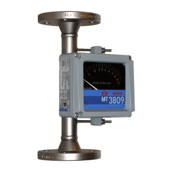
1-1 Description The Brooks ® Models MT 3809 and MT 3819 Variable Area Flowmeters are rugged, all metal flowmeters offering 2% full scale accuracy. The Model MT 3809 is constructed with stainless steel components for measuring a variety of gas, liquid and steam applications while the Model MT 3819 utilizes a ETFE (Tefzel™) lining for aggressive liquid and gas applications. - Page 8 September, 2008 Repeatability 0.25% Full Scale Pressure Ratings Refer to Table 1-2 for Model MT 3809 maximum non-shock pressure. Model MT 3819 pressure rating is dependant on flange rating. Pressure Equipment Directive (PED) 97/23/EC Flow meter complies under Sound Engineering...
- Page 9 Enclosure NEMA 4X construction MT 3809 and MT 3819 Standard Housing: Die cast aluminum, polyurethane paint with glass window MT 3809 and MT 3819 Optional Housing: 316L stainless steel with gritblast and glass window; epoxy paint for aluminum housing Meter Dimensions...
- Page 10 Section 1 Introduction Installation and Operation Manual X-VA-MT3809-3819-eng Part Number: 541B049AHG Models MT 3809 & 3819 September, 2008 Table 1-1A Model MT 3809 Capacities, Pressure Drop and Viscosity Immunity Ceiling CONNECTION SIZE FLOAT MATERIAL STAINLESS STEEL 316L METER ANSI FLOAT...
- Page 11 Section 1 Introduction Installation and Operation Manual X-VA-MT3809-3819-eng Part Number: 541B049AHG Models MT 3809 & 3819 September, 2008 Table 1-2 Model MT 3809 Pressure Ratings* 316/316L Stainless Steel (psig at indicated temperature) Flange Rating** 600°F 617°F -20°F to 100°F 200°F 300°F...
-
Page 12: Models Mt 3809 And Mt 3819 Dimensions
** Weights shown for aluminum indicator and PN40/50 lb flanges. Add 1.7 kg (3.8 lbs.) for steel indicator housing. ***Model MT 3809 meters with explosion proof transmitters and 300# oversized flanges or 600# regular and oversized flanges have a 300mm lay length. -
Page 13: Optional Accessories
1-4 Optional Accessories Needle control valves, sight flow indicators and flow controllers (available on the MT 3809 only) For flow rate control, needle control valves or flow controllers may be externally piped into the inlet or outlet side of the instrument. - Page 14 Section 1 Introduction Installation and Operation Manual X-VA-MT3809-3819-eng Part Number: 541B049AHG Models MT 3809 & 3819 September, 2008 In operation the microprocessor transmitter converts the measured process flow into a 4-20mA output with HART protocol. The signal originates when the float magnet inside the metering tube passes a magnetic sensor mounted on the transmitter.
-
Page 15: Power Supply Vs. Maximum Load Resistance
Section 1 Introduction Installation and Operation Manual X-VA-MT3809-3819-eng Part Number: 541B049AHG Models MT 3809 & 3819 September, 2008 Non-Incendive United States and Canada UL Listed, E73889, Vol. 1, Sect. 15 Class I, II, III, Division 2, Groups A, B, C,D F, and G; T4 Europe –... - Page 16 Section 1 Introduction Installation and Operation Manual X-VA-MT3809-3819-eng Part Number: 541B049AHG Models MT 3809 & 3819 September, 2008 Two Alarm Outputs (open collector) Optically isolated outputs assignable to alarms, reverse flow indicator, or manual valve. Maximum off-state voltage: 30 Vdc Maximum off-state current: 0.05 mA...
-
Page 17: Transmitter Only Wiring Diagram
Section 1 Introduction Installation and Operation Manual X-VA-MT3809-3819-eng Part Number: 541B049AHG Models MT 3809 & 3819 September, 2008 Ref. No.981Y006 - Rev. F Sheet 1 of 2 Figure 1-3 Transmitter Only Wiring Diagram 1-11... -
Page 18: Transmitter Only Wiring Notes
Section 1 Introduction Installation and Operation Manual X-VA-MT3809-3819-eng Part Number: 541B049AHG Models MT 3809 & 3819 September, 2008 Ref. No.981Y006 - Rev. F Sheet 2 of 2 Figure 1-4 Transmitter Only Wiring Notes 1-12... -
Page 19: Transmitter With Alarm And Pulse Outputs Wiring Diagram
Section 1 Introduction Installation and Operation Manual X-VA-MT3809-3819-eng Part Number: 541B049AHG Models MT 3809 & 3819 September, 2008 Ref. No.981Y005 - Rev. F Sheet 1 of 2 Figure 1-5 Transmitter with Alarm and Pulse Outputs Wiring Diagram 1-13... - Page 20 Section 1 Introduction Installation and Operation Manual X-VA-MT3809-3819-eng Part Number: 541B049AHG Models MT 3809 & 3819 September, 2008 Ref. No.981Y005 - Rev. F Sheet 2 of 2 Figure 1-6 Transmitter with Alarm and Pulse Outputs Wiring Diagram 1-14...
-
Page 21: Model Mt3809 Explosion-Proof Housing Wiring Diagram
Section 1 Introduction Installation and Operation Manual X-VA-MT3809-3819-eng Part Number: 541B049AHG Models MT 3809 & 3819 September, 2008 Ref. No.981Y008 - Rev. D Sheet 1 of 1 Figure 1-7 Model MT3809 Explosion-Proof Housing Wiring Diagram 1-15... -
Page 22: Microprocessor Transmitter With Inductive Alarms
Section 1 Introduction Installation and Operation Manual X-VA-MT3809-3819-eng Part Number: 541B049AHG Models MT 3809 & 3819 September, 2008 1-7 Microprocessor Transmitter with Inductive Alarms This combined system provides both the sophistication of the microprocessor along with the simplicity of one or two switch inductive alarms. -
Page 23: Transmitter With Inductive Alarm Wiring Notes
Section 1 Introduction Installation and Operation Manual X-VA-MT3809-3819-eng Part Number: 541B049AHG Models MT 3809 & 3819 September, 2008 Ref. No.981Y007 - Rev. F Sheet 2 of 2 Figure 1-9 Transmitter with Inductive Alarm Wiring Notes 1-17... -
Page 24: Inductive Alarm Switches
Section 1 Introduction Installation and Operation Manual X-VA-MT3809-3819-eng Part Number: 541B049AHG Models MT 3809 & 3819 September, 2008 1-8 Inductive Alarm Switches A. Design • 1 or 2 normally open inductive limit switches • Optional intrinsically safe power supply/amplifier/relay unit •... - Page 25 Section 1 Introduction Installation and Operation Manual X-VA-MT3809-3819-eng Part Number: 541B049AHG Models MT 3809 & 3819 September, 2008 Explosion- proof/ Flame-proof United States and Canada UL Listed, E73889, Vol. 1, Sect. 14 Class I, Division 1, Groups C, D; Dust Ignition-proof, Class II, Division 1, Groups E, F, G; Class III; T4 Europe –...
-
Page 26: Inductive Alarms Only Wiring Diagram
Section 1 Introduction Installation and Operation Manual X-VA-MT3809-3819-eng Part Number: 541B049AHG Models MT 3809 & 3819 September, 2008 Ref. No.981Y001 - Rev. F Sheet 1 of 2 Figure 1-10 Inductive Alarms Only Wiring Diagram 1-20... -
Page 27: Inductive Alarms Only Wiring Notes
Section 1 Introduction Installation and Operation Manual X-VA-MT3809-3819-eng Part Number: 541B049AHG Models MT 3809 & 3819 September, 2008 Ref. No.981Y001 - Rev. D Sheet 2 of 2 Figure 1-11 Inductive Alarms Only Wiring Notes 1-21... - Page 28 Section 1 Introduction Installation and Operation Manual X-VA-MT3809-3819-eng Part Number: 541B049AHG Models MT 3809 & 3819 September, 2008 THIS PAGE WAS INTENTIONALLY LEFT BLANK 1-22...
-
Page 29: Section 2 Installation
Installation and Operation Manual Section 2 Installation X-VA-MT3809-3819 Part Number: 541B049AHG Models MT 3809 & 3819 September, 2008 2-1 General This section contains the procedures for the receipt and installation of the instrument. See Section 1 for dimensional and connection requirements. -
Page 30: Return Shipment
Instrument must have been purged in accordance with the following: Completion of form RPR003-1, Brooks Instrument Decontamination Statement. A copy of this form can be downloaded from the Brooks website www.brooksinstrument.com or is available from any Brooks Instrument location listed above. This is required before any Brooks Personnel can begin processing. -
Page 31: Installation Of Flowmeter
Failure to do so may result in thermal expansion of the liquid which can rupture the meter and cause possible personal injury. Recommended installation for Models MT 3809 and MT 3819 is as follows: a. Carefully remove the covers from each end of the flowmeter. -
Page 32: Transmitter With Or Without Optional Alarms And Pulse Output
Models MT 3809 & 3819 September, 2008 2-8 Installation of Models MT 3809 and MT 3819 Flowmeters with a Smart Meter Manager Transmitter with or without Optional Alarms and Pulse Output a. Install the meter as described in Section 2-4. -
Page 33: Smart Meter Manager Electrical Configuration
Installation and Operation Manual Section 2 Installation X-VA-MT3809-3819 Part Number: 541B049AHG Models MT 3809 & 3819 September, 2008 ® inside Smart Met e r Manager Figure 2-2 Smart Meter Manager Electrical Configuration ® inside Smart Met e r Manager Figure 2-3 Typical SMM Transmitter Analog Output and Power Wiring... -
Page 34: Multi-Drop Smm Transmitter Analog Output And Power Wiring
Section 2 Installation Installation and Operation Manual X-VA-MT3809-3819-eng Part Number: 541B049AHG Models MT 3809 & 3819 September, 2008 ® inside Smart Met e r Manager Figure 2-4 Alternate SMM Transmitter Analog Output and Power Wiring (Where 4-20 mA signal is not required) ®... - Page 35 Figure 1-3. Alternatively, the optional intrinsically safe power supply available from Brooks may be used. Cable parameters for inductance and capacitance still apply. 2. If the area classification is Division 2, a barrier is not required and cable parameters are not applicable.
-
Page 36: Typical Smm Transmitter With Alarms And Pulse Digital Output And Power Wiring
Refer to Figure 3-2 for connection instructions. Note: The Brooks SMM transmitter device description (DD) will not be programmed into the Emerson Model 275 hand-held communicators until after Summer 1997. Until the Brooks device description becomes... - Page 37 Installation and Operation Manual Section 2 Installation X-VA-MT3809-3819 Part Number: 541B049AHG Models MT 3809 & 3819 September, 2008 All internal parameters can be accessed over the HART communications channel, including the configuration of the output signals used for alarms and pulse output. An external termination box is attached for easy hookup of these signals.
-
Page 38: Transmitter With Inductive Alarms (1 Or 2 Switches)
Install the transmitter as described in Section 2-8. c. Install the inductive alarms as indicated below Section 2-10. 2-10 Installation of Models MT 3809 and MT 3819 Flowmeters with Inductive Alarms (1 or 2 Switches) CAUTION Since this is a magnetically activated device, strong magnetic fields and materials with magnetic properties may cause faulty operation when in close proximity to the flowmeter. - Page 39 Installation and Operation Manual Section 2 Installation X-VA-MT3809-3819 Part Number: 541B049AHG Models MT 3809 & 3819 September, 2008 1. The inductive alarms can be supplied as a stand alone option or combined with the transmitter. When stand alone, connections to the alarms are made inside the indicator housing.
- Page 40 Section 2 Installation Installation and Operation Manual X-VA-MT3809-3819-eng Part Number: 541B049AHG Models MT 3809 & 3819 September, 2008 THIS PAGE WAS INTENTIONALLY LEFT BLANK 2-12...
-
Page 41: Section 3 Operation
Section 3 Operation Installation and Operation Manual X-VA-MT3809-3819-eng Part Number: 541B049AHG Models MT 3809 and 3819 September, 2008 3-1 Pre-Start Check After the flowmeter has been properly installed in the process, it is ready for operation. When initiating flow, slowly open the valve to avoid a flow surge.Bypass is a help in bringing the flow on smoothly. -
Page 42: Transmitter With Or Without Optional Alarms And Pulse Output For Totalization
Models MT 3809 and 3819 September, 2008 3-3 Operation of the Models MT 3809 and MT 3819 Flowmeters with a Smart Meter Manager Transmitter with or without Optional Alarms and Pulse Output for totalization a. Start-up the meter as described in Section 3-2. -
Page 43: Models Mt 3809 And Mt 3819 Smm Electronics Device Description Tree (Basic Setup)
Set OFF Totalizers FlowRate Alarm End Test Pulse Output Test Resettable Alarm HiLimit Alarm LoLimit Output n Pulses End Test Inventory Outputs Alarms Device Information Figure 3-1 Models MT 3809 and MT 3819 SMM Electronics Device Description Tree (Basic Setup) -
Page 44: Models Mt 3809 And Mt 3819 Smm Electronics Device Description Tree (Detailed Setup)
ExternalTerminationBox Calibration Viscosity Accuracy Class Temperature Temperature UOM Observed Temperature Density Density UOM Observed Density Pressure Pressure UOM Observed Pressure Viscosity Viscosity UOM Observed Viscosity Figure 3-2 Models MT 3809 and MT 3819 SMM Electronics Device Description Tree (Detailed Setup) -
Page 45: Hart Communicator
Section 3 Operation Installation and Operation Manual X-VA-MT3809-3819-eng Part Number: 541B049AHG Models MT 3809 and 3819 September, 2008 The HART Communicator is the hand-held interface that provides a common communication link to all HART compatible, microprocessor- based devices. A keypad, liquid crystal display (LCD) and software menu structure make up the HART communicator user interface. -
Page 46: Hart Communicator Action / Hot Keys
Section 3 Operation Installation and Operation Manual X-VA-MT3809-3819-eng Part Number: 541B049AHG Models MT 3809 and 3819 September, 2008 Emerson Model 275 Communicator Functions Action Keys and Hot Key Six Action Keys promote easy navigation through the menu structure. You may customize the Hot Key to quickly access a menu of your most frequently performed on-line tasks. - Page 47 Section 3 Operation Installation and Operation Manual X-VA-MT3809-3819-eng Part Number: 541B049AHG Models MT 3809 and 3819 September, 2008 Function Keys Use the four function keys, marked F1 through F4 located below the LCD to perform software functions as indicated by the dynamic labels. Different labels appear over the four function keys as you move among the various menus.
- Page 48 Section 3 Operation Installation and Operation Manual X-VA-MT3809-3819-eng Part Number: 541B049AHG Models MT 3809 and 3819 September, 2008 Transmitter Analog Output: Analog Output HiRange, Analog Output LoRange d. Optional Programmable Alarm and Pulse Output Parameters and Features Alarm Contact Output: HiLimit, LoLimit One or two digital outputs are available for a alarm signals.
- Page 49 Section 3 Operation Installation and Operation Manual X-VA-MT3809-3819-eng Part Number: 541B049AHG Models MT 3809 and 3819 September, 2008 not be disabled or turned off. When an alarm occurs, it can be posted through the defined ‘destination’ digital contact closure outputs #1, #2 both or neither. Therefore the alarms may be managed according to local operating practices and the need to notify upstream control/safety systems.
- Page 50 Section 3 Operation Installation and Operation Manual X-VA-MT3809-3819-eng Part Number: 541B049AHG Models MT 3809 and 3819 September, 2008 Brooks MT 38xxVA Detailed Setup 1 Measurements 2 Computations From the Detailed Setup Menu, 3 Outputs select Measurements. 4 Alarms 5 Device Info...
- Page 51 Section 3 Operation Installation and Operation Manual X-VA-MT3809-3819-eng Part Number: 541B049AHG Models MT 3809 and 3819 September, 2008 Brooks MT 38xxVA Flow 1 FlowRate Units 2 Configuration 3 Meter Calibration From the Flow Menu, select FlowRate Units of Measure SAVE (FlowRate UOM).
- Page 52 Section 3 Operation Installation and Operation Manual X-VA-MT3809-3819-eng Part Number: 541B049AHG Models MT 3809 and 3819 September, 2008 Brooks MT 38xxVA Device Setup 1 Process Variables 2 Diags & Services 3 Basic Setup 4 Detailed Setup From the Device Setup Menu, select Basic Setup.
-
Page 53: Transmitter With Inductive Alarms (1 Or 2 Switches)
(F2) to send this information to the transmitter. 3-4 Operation of the Models MT 3809 and MT 3819 Flowmeters with a Smart Meter Manager Transmitter with Inductive Alarms ( 1 or 2 Switches) a. Start-up the meter as described in Section 3-2. - Page 54 Section 3 Operation Installation and Operation Manual X-VA-MT3809-3819-eng Part Number: 541B049AHG Models MT 3809 and 3819 September, 2008 THIS PAGE WAS INTENTIONALLY LEFT BLANK 3-14...
-
Page 55: General Service Information
Section 4 Maintenance Installation and Operation Manual X-VA-MT3809-3819-eng Part Number: 541B049AHG Models MT 3809 and 3819 September, 2008 4-1 General Service Information... -
Page 56: 4-2A Meter Float Replacement And Cleaning (Mt 3809)
Process line pressure should be removed prior to servicing. There is no routine maintenance required for the Models MT 3809 and MT 3819 flowmeters. However should it become necessary to replace, adjust or remove components of the flowmeter, specific recommendations must be followed. - Page 57 Section 4 Maintenance Installation and Operation Manual X-VA-MT3809-3819-eng Part Number: 541B049AHG Models MT 3809 and 3819 September, 2008 meter inlet. Loosen the float assembly with two screwdrivers one on each end of the meter and turn to loosen the inlet and outlet screws (#2). Remove inlet screw (#2) at the bottom of the meter.
- Page 58 Section 4 Maintenance Installation and Operation Manual X-VA-MT3809-3819-eng Part Number: 541B049AHG Models MT 3809 and 3819 September, 2008 outlet screw (#5). Push the float assembly out through the inlet/bottom. To clean the gas damper, unscrew the cylinder head (#6). Then remove the bolt (#7) and carefully take out the small piston so as to not damage the critical surfaces.
- Page 59 Section 4 Maintenance Installation and Operation Manual X-VA-MT3809-3819-eng Part Number: 541B049AHG Models MT 3809 and 3819 September, 2008 the float assembly up and out the top/outlet side. Reassemble by inserting the float assembly into the top of the meter. Replace the guide vane (#3) and secure the float assembly by tightening the inlet and outlet screws (#2).
- Page 60 Section 4 Maintenance Installation and Operation Manual X-VA-MT3809-3819-eng Part Number: 541B049AHG Models MT 3809 and 3819 September, 2008 Liquid Service Gas Service Figure 4-1 Meter Float Replacement & Cleaning (MT 3809)
-
Page 61: Exploded View, Model Mt 3809, Size 15 (Gas Or Liquid Service)
Installation and Operation Manual X-VA-MT3809-3819-eng Part Number: 541B049AHG Models MT 3809 and 3819 September, 2008 Figure 4-2 Exploded View, Model MT 3809, Size 15 ( Gas or Liquid Service Only) Figure 4-3 Exploded View, Model MT 3809, Size 16 ( Liquid Service Only) -
Page 62: 4-2B Meter Float Replacement And Cleaning (Mt 3819)
Section 4 Maintenance Installation and Operation Manual X-VA-MT3809-3819-eng Part Number: 541B049AHG Models MT 3809 and 3819 September, 2008 4-2b Meter Float Replacement and Cleaning (MT 3819) Flanged Connections, All Sizes, Liquid or Gas 1. Remove the meter from the process line and lay the meter horizontal on a table. - Page 63 Section 4 Maintenance Installation and Operation Manual X-VA-MT3809-3819-eng Part Number: 541B049AHG Models MT 3809 and 3819 September, 2008 support. e. Place the switch on the bracket with the open end facing towards the center of the scale plate and the wires facing away from the scale plate.
-
Page 64: Smm Transmitter Replacement With Inductive Alarms
The transmitter is a self contained unit matched specifically to the associated flowmeter. If there is a need to replace it, please contact your nearest authorized Brooks Service Representative. However, the inductive alarms may be replaced according to the procedure in Section 4-5. - Page 65 CE mærkning af Masse Flow udstyr Dato Januar-1996. Brooks Instrument har gennemført CE mærkning af elektronisk udstyr med succes, i henhold til regulativet om elektrisk støj (EMC direktivet 89/336/EEC). Der skal dog gøres opmærksom på benyttelsen af signalkabler i forbindelse med CE mærkede udstyr.
- Page 66 Date January-1996. The Brooks (electric/electronic) equipment bearing the CE mark has been successfully tested to the regulations of the Electro Magnetic Compatibility (EMC directive 89/336/EEC). Special attention however is required when selecting the signal cable to be used with CE marked equipment.
- Page 67 Janvier 1996. Messieurs, Les équipements Brooks (électriques/électroniques) portant le label CE ont été testés avec succès selon les règles de la Compatibilité Electromagnétique (directive CEM 89/336/EEC). Cependant, la plus grande attention doit être apportée en ce qui concerne la sélection du câble utilisé pour véhiculer le signal d’un appareil portant le label CE.
- Page 68 CE. Qualità dei cavi di segnale e dei relativi connettori: Brooks fornisce cavi di elevata qualità che soddisfano le specifiche richieste dalla certificazione CE. Se l’utente intende usare propri cavi, questi devono possedere una schermatura del 100%.
- Page 69 UTFØRELSE AV SIGNALKABEL OG TILHØRENDE PLUGGER: • Brooks Instrument tilbyr levert med utstyret egnet kabel som møter de krav som stilles til CE-sertifisering. • Dersom kunden selv velger kabel, må kabel med fullstendig, 100% skjerming av lederene benyttes.
- Page 70 Date : January 1996 Brooks (elektriska / elektronik) utrustning, som är CE-märkt, har testats och godkänts enligt gällande regler för elektromagnetisk kompabilitet (EMC direktiv 89/336/EEC). Speciell hänsyn måste emellertid tas vid val av signalkabel som ska användas tillsammans med CE-märkt utrustning.
- Page 71 Installation and Operation Manual X-VA-MT3809-3819-eng Part Number: 541B049AHG Models MT 3809 and 3819 September, 2008 THIS PAGE WAS INTENTIONALLY LEFT BLANK...
- Page 72 BROOKS SERVICE AND SUPPORT Brooks is committed to assuring all of our customers receive the ideal flow solution for their application, along with outstanding service and support to back it up. We operate first class repair facilities located around the world to provide rapid response and support.
Need help?
Do you have a question about the MT 3809 and is the answer not in the manual?
Questions and answers