Table of Contents
Advertisement
Advertisement
Table of Contents

Related Manuals for Brooks Glass Tube Full-View 1110


Summary of Contents for Brooks Glass Tube Full-View 1110
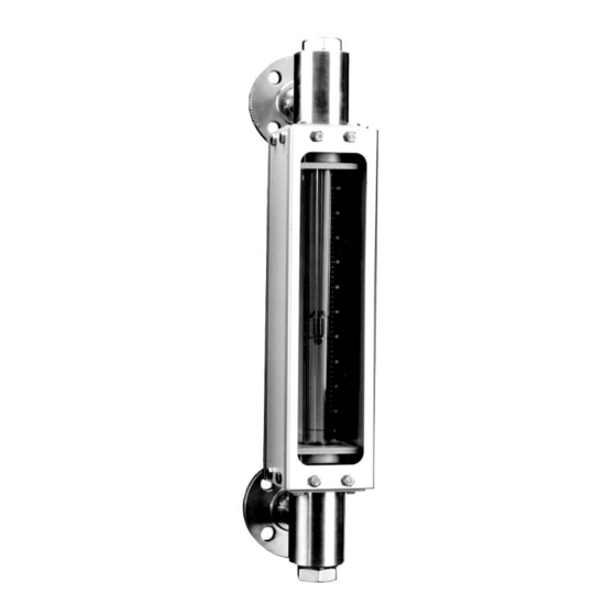
- Page 1 Installation and Operation Manual X-VA-1110-1140-eng Part Number: 541B040AHG ® Brooks 1110 and 1140 Series March, 2008 ® Glass Tube Full-View Flowmeters Model 1110 Model 1140 Full-View Flowmeter Full-View Flowmeter (NPT Connections) (Flange Connections)
- Page 2 Essential Instructions Read this page before proceeding! Brooks Instrument designs, manufactures and tests its products to meet many national and international standards. Because these instruments are sophisticated technical products, you must properly install, use and maintain them to ensure they continue to operate within their normal specifications.
- Page 3 We appreciate this opportunity to service your flow measurement and control requirements with a Brooks Instrument device. Every day, flow customers all over the world turn to Brooks Instrument for solutions to their gas and liquid low-flow applications. Brooks provides an array of flow measurement and control products for various industries from biopharmaceuticals, oil and gas, fuel cell research and chemicals, to medical devices, analytical instrumentation, semiconductor manufacturing, and more.
- Page 4 Installation and Operation Manual X-VA-1110-1140-eng Part Number: 541B040AHG ® Brooks 1110 and 1140 Series March, 2008 THIS PAGE WAS INTENTIONALLY LEFT BLANK...
-
Page 5: Table Of Contents
Contents Installation and Operation Manual X-VA-1110-1140-eng Part Number: 541B040AHG ® Brooks 1110 and 1140 Series March, 2008 Paragraph Page Number Number Section 1 Introduction 1-1 Description ............................1-1 1-2 Design Features ..........................1-1 1-3 Specifications ............................. 1-1 1-4 Optional Equipment (Mountings, Valves and Flow Controllers) ............1-7 Section 2 Installation 2-1 General .............................. - Page 6 Contents Installation and Operation Manual X-VA-1110-1140-eng Part Number: 541B040AHG ® Brooks 1110 and 1140 Series March, 2008 Figures Figure Page Number Number 1-1 Dimensions 127mm & 250mm Full-View Flowmeters ................ 1-6 1-3 Float Types ............................1-7 2-1 Typical Bypass Installation ......................... 2-3 3-1 Typical Bypass Installation .........................
-
Page 7: Section 1 Introduction
1110 and 1140 Series March, 2008 1-1 Description ® ® The Brooks Full-View glass tube meters are designed to offer a wide variety of meter configurations to meet a broad range of metering applications. The packing gland seal construction provides for long-term, leak-free, and reliable flow measurement. - Page 8 Installation and Operation Manual Section 1 Introduction X-VA-1110-1140-eng Part Number: 541B040AHG Brooks ® 1110 and 1140 Series March, 2008 Accuracy Standard Flow Accuracy (127, 150, 250mm Tubes): ±2% Full Scale Optional Flow Accuracy (127, 150, 250mm Tubes): ±1% Full Scale Repeatability 0.5% Full Scale...
- Page 9 Installation and Operation Manual Section 1 Introduction X-VA-1110-1140-eng Part Number: 541B040AHG ® Brooks 1110 and 1140 Series March, 2008 WARNING GLASS TUBE EXPLOSION HAZARD Plastic protective sleeve must remain over glass tube. (Meter sizes 7 -13 only) Fasten meter windows securely.
- Page 10 Installation and Operation Manual Section 1 Introduction X-VA-1110-1140-eng Part Number: 541B040AHG Brooks ® 1110 and 1140 Series March, 2008 Housing and Window Bezel Standard: Aluminum with polyurethane paint. Optional: 18-8 stainless steel. End Fittings 316 stainless steel,steel, Hastelloy C, CPVC Sizes 2-8, PVC Sizes 9-10, brass.
-
Page 11: Connections
Installation and Operation Manual Section 1 Introduction X-VA-1110-1140-eng Part Number: 541B040AHG ® Brooks 1110 and 1140 Series March, 2008 Table 1-2 Connections Model 1110 Model 1114 Model 1140 Model 1144 Meter Inlet&Outlet Inlet&Outlet Inlet&Outlet Inlet&Outlet Size Horizontal Vertical Horizontal Vertical... -
Page 12: Dimensions 127Mm & 250Mm Full-View Flowmeters
Installation and Operation Manual Section 1 Introduction X-VA-1110-1140-eng Part Number: 541B040AHG Brooks ® 1110 and 1140 Series March, 2008 All Dimensions in Inches 1110 - 1140 1114 1144 Nominal Nominal Meter Scale Length Scale Length Nominal Scale Length (MM) Meters... -
Page 13: Optional Equipment (Mountings, Valves And Flow Controllers)
• Valves: Available for connection sizes 1/4” through 1” only. Horizontal stem in outlet or inlet and fitting Sizes 2 through 10. • Flow Controller: Brass or 316 Stainless steel integrally piped to Sizes 2-6. See Brooks publication DS-FCA. READ HERE... -
Page 14: Capacities, 150Mm Scale, Rib Guided Tube, Spherical Float
Installation and Operation Manual Section 1 Introduction X-VA-1110-1140-eng Part Number: 541B040AHG Brooks ® 1110 and 1140 Series March, 2008 Table 1-3 Capacities, Table 1-4 Capacities, 150mm Scale, Rib Guided Tube, Spherical Float 250mm Scale, Rib Guided Tube, Spherical Float MAXIMUM FLOW RATE... -
Page 15: Capacities, 250Mm Scale, Rib Guided Tube, Standard Float
Installation and Operation Manual Section 1 Introduction X-VA-1110-1140-eng Part Number: 541B040AHG ® Brooks 1110 and 1140 Series March, 2008 Table 1-5 Capacities, 250mm Scale , Rib Guided Tubes, Standard Float Water Air @ 14.7 psia and 70°F (21°C) Pressure Viscosity... -
Page 16: Capacities, 127Mm Scale, Rib Guided Tubes, Standard Float
Installation and Operation Manual Section 1 Introduction X-VA-1110-1140-eng Part Number: 541B040AHG Brooks ® 1110 and 1140 Series March, 2008 Table 1-6 Capacities, 127mm Scale, Rib Guided Tubes, Standard Float Water Air @ 14.7 psia and 70°F (21°C) Pressure Viscosity Pressure... -
Page 17: Capacities, 250Mm Scale, Plain Tapered Tubes, Rod Guided Float
Installation and Operation Manual Section 1 Introduction X-VA-1110-1140-eng Part Number: 541B040AHG ® Brooks 1110 and 1140 Series March, 2008 Table 1-7 Capacities, 250mm Scale, Plain Tapered Tubes, Rod Guided Float Water Air @ 14.7 psia and 70°F (21°C) Pressure Viscosity... - Page 18 Installation and Operation Manual Section 1 Introduction X-VA-1110-1140-eng Part Number: 541B040AHG Brooks ® 1110 and 1140 Series March, 2008 THIS PAGE WAS INTENTIONALLY LEFT BLANK 1-12...
-
Page 19: Section 2 Installation
If the packing case is damaged, the local carrier should be notified at once regarding his liability. A report should be submitted to your nearest Product Service Department. Brooks Instrument 407 W. Vine Street P.O. Box 903... -
Page 20: Return Shipment
Material Safety Data Sheet (MSDS) for the fluid(s) used in the instrument. Failure to provide this information will delay processing by Brooks personnel. Copies of these forms can be downloaded from the Brooks website www.BrooksInstrument.com or are available from any Brooks Instrument location listed above. -
Page 21: Installation Of Meter
Installation of a bypass piping arrangement is strongly recommended, Figure 2-1. Bypass piping permits the meter to be isolated from the flow line for servicing and cleaning. For more details refer to Brooks T-023 Technical Bulletin Guide for bypass meters. - Page 22 Section 2 Installation Installation and Operation Manual X-VA-1110-1140-eng Part Number: 541B040AHG ® Brooks 1110 and 1140 Series March, 2008 THIS PAGE WAS INTENTIONALLY LEFT BLANK...
-
Page 23: Section 3 Operation
Installation and Operation Manual Section 3 Operation X-VA-1110-1140-eng Part Number: 541B040AHG ® Brooks 1110 and 1140 Series March, 2008 3-1 General After the flowmeter has been properly installed in the process, it is ready for operation. When initiating flow, slowly open the valve to avoid a flow surge.Bypass is a help in bringing the flow on smoothly. -
Page 24: Typical Bypass Installation
Installation and Operation Manual Section 3 Operation X-VA-1110-1140-eng Part Number: 541B040AHG ® Brooks 1110 and 1140 Series March, 2008 To initiate flow through a flowmeter using bypass piping, refer to Figure 3-1. 1. Close flowmeter isolation valves (A) and (B). -
Page 25: Section 4 Maintenance And Cleaning
Installation and Operation Manual Section 4 Maintenance and Cleaning X-VA-1110-1140-eng Part Number: 541B040AHG ® Brooks 1110 and 1140 Series March, 2008 4-1 General This section provides the assembly and disassembly procedures for the Brooks Full-View flowmeters. -
Page 26: Disassembly And Reassembly
Installation and Operation Manual Section 4 Maintenance and Cleaning X-VA-1110-1140-eng Part Number: 541B040AHG ® Brooks 1110 and 1140 Series March, 2008 4-2 Disassembly and Reassembly Note: Step number preceded by an asterisk (*) apply only to rod guided floats. A. Disassembly 1. - Page 27 Installation and Operation Manual Section 4 Maintenance and Cleaning X-VA-1110-1140-eng Part Number: 541B040AHG ® Brooks 1110 and 1140 Series March, 2008 4. Install the gland followers, polycarbonate sleeve, Size 7 (1/2") and larger, gland rings, and packing on the tube.
- Page 28 Installation and Operation Manual Section 4 Maintenance and Cleaning X-VA-1110-1140-eng Part Number: 541B040AHG ® Brooks 1110 and 1140 Series March, 2008 THIS PAGE WAS INTENTIONALLY LEFT BLANK...
- Page 29 Installation and Operation Manual Section 5 Accessories X-VA-1110-1140-eng Part Number: 541B040AHG ® Brooks 1110 and 1140 Series March, 2008 5-1 General See Optional Equipment, Section 1-4, for specifications, dimensions, and options. Refer to both parts of Figures 5-1a thru 5-1c and Table 5-1 for exploded drawing and parts.
- Page 30 Installation and Operation Manual Section 5 Accessories X-VA-1110-1140-eng Part Number: 541B040AHG ® Brooks 1110 and 1140 Series March, 2008 Figure 5-1a Model 1110 Exploded Parts Drawing...
- Page 31 Installation and Operation Manual Section 5 Accessories X-VA-1110-1140-eng Part Number: 541B040AHG ® Brooks 1110 and 1140 Series March, 2008 Figure 5-1b Model 1110 Exploded Parts Drawing (Continued)
- Page 32 Installation and Operation Manual Section 5 Accessories X-VA-1110-1140-eng Part Number: 541B040AHG ® Brooks 1110 and 1140 Series March, 2008 Figure 5-1c Model 1110 Exploded Parts Drawing (Continued)
- Page 33 Installation and Operation Manual X-VA-1110-1140-eng Part Number: 541B040AHG ® Brooks 1110 and 1140 Series March, 2008 THIS PAGE WAS INTENTIONALLY LEFT BLANK...
- Page 34 Seller. BROOKS LOCAL AND WORLDWIDE SUPPORT Brooks Instrument provides sales and service facilities around the world, ensuring quick delivery from local stock, timely repairs and locally based sales and service facilities.
Need help?
Do you have a question about the Glass Tube Full-View 1110 and is the answer not in the manual?
Questions and answers