Table of Contents

Related Manuals for Brooks 5850S


Summary of Contents for Brooks 5850S
- Page 1 Installation and Operation Manual X-DPT-Profibus-Interface-eng PN 541-C-068-AAG November, 2008 Profibus-DP Interface ® for use with Brooks Smart Mass Flow Meters models 5860S, 5861S, 5863S, 5864S & Mass Flow Controllers models 5850S, 5851S, 5853S...
- Page 2 Read this page before proceeding! Brooks Instrument designs, manufactures and tests its products to meet many national and international standards. Because these instruments are sophisticated technical products, you must properly install, use and maintain them to ensure they continue to operate within their normal specifications.
- Page 3 We appreciate this opportunity to service your flow measurement and control requirements with a Brooks Instrument device. Every day, flow customers all over the world turn to Brooks Instrument for solutions to their gas and liquid low-flow applications. Brooks provides an array of flow measurement and control products for various industries from biopharmaceuticals, oil and gas, fuel cell research and chemicals, to medical devices, analytical instrumentation, semiconductor manufacturing, and more.
-
Page 4: Table Of Contents
2.3 Recommended Storage Practice ..................10 2.4 Return Shipment ......................10 2.5 Gas Connectionsl ......................10 2.6 The Brooks Smart Mass flow products ................11 2.7 Profibus on the Smart TMF series ................. 12 INSTALLATION ....................... 14 3.1 Installation ........................14 3.2 Electrical interfacing ...................... - Page 5 Installation and Operation Manual X-DPT-Profibus-Interface-eng PN 541-C-068-AAG November, 2008 TABLES Table 2-1: Brooks Smart Mass Flow Meters and Controllers..........11 Table 3-1: Smart TMF main connector pin layout..............15 Table 3-2: Smart TMF Profibus-DP network connector pin layout........... Table 3-3: Supported baud rate values.................
-
Page 6: Introduction
HOW TO USE THIS MANUAL This instruction manual is intended to provide the user with all the necessary information to operate and program the Brooks Instrument Smart Mass Flow Meters and Controllers on a Profibus-DP network. This manual should be used together to the Installation and Operating Manual Smart TMF series (Brooks Instrument doc. -
Page 7: Definition Of Terms
Installation and Operation Manual X-DPT-Profibus-Interface-eng PN 541-C-068-AAG November, 2008 DEFINITION OF TERMS 1.3.1 Terminology GSD file The GSD file contains the characteristic device data of the product, i.e. the device profile. Input/Output Profibus-DP conventions define all input/output directions as seen from the master system. Data transferred by the master to the slave (e.g. -
Page 8: Number Representations And Formats
Installation and Operation Manual X-DPT-Profibus-DP-Interface-eng PN 541-C-068-AAG November, 2008 1.3.2 Number representations and formats Smallest binary information representation: 0 or 1 Nibble Binary number representation, consists of 4 bits. Repre sents 1 value or 4 situations (‘bitmapped’). Usually nibbles appear grouped together in one or more bytes (i.e. -
Page 9: Product Overview
If the packing case is damaged, the local carrier should be notified at once regarding his liability. A report should be submitted to your nearest Product Service Department. Brooks Instrument 407 W. Vine Street P.O. Box 903... -
Page 10: Recommended Storage Practice
In addition, the device should be subjected to a pneumatic pressure test in accordance with the applicable vessel codes. 2.4 Return Shipment Prior to returning any instrument to the factory, contact your nearest Brooks location for a Return Materials Authorization Number (RMA#). This can be obtained from one of the following locations: Brooks Instrument 407 W. -
Page 11: The Brooks Smart Mass Flow Products
MF63 and 5864/MF64 measure gas flow accurately. The heart of the system, is the thermal mass flow sensor which produces an electrical output signal as a function of flow rate. In addition the Brooks Smart Mass Flow Controllers, models 5850/MF50, 5851/MF51 and 5853/MF53 are equipped with an electro- mechanical valve, allowing them to control gas flows. -
Page 12: Profibus On The Smart Tmf Series
Profibus-DP features and function in more detail. PROFIBUS ON THE SMART TMF SERIES The Profibus piggyback board on the Brooks Smart TMF series is provided with all the necessary hardware and software to implement Profibus-DP functionality on an RS-485 network according to the EN 50170 Profibus standard. The Profibus piggyback board is equipped with an additional 9-pin sub-D connector for the 58.. - Page 13 Installation and Operation Manual X-DPT-Profibus-Interface-eng PN 541-C-068-AAG November, 2008 • Global control commands (e.g. fail safe, sync). • Get configuration (i.e. read number of I/O bytes and composition). • Read diagnostics information (i.e. get error and alarm status). • Set parameters (i.e. select gas number, engineering units, I/O configuration •...
-
Page 14: Installation
If these pins are not used, the installed piggyback will have to provide a separate interface (connector) to allow connection to the network. In the case of the Profibus-DP interface for the Brooks Smart Mass Flow Meter/ Controller models, pin 14 and 15 on the main connector are not used. The installed piggyback board will provide a separate connector for network connec- tions. -
Page 15: Table 3-1: Smart Tmf Main Connector Pin Layout
Table 3-1: Smart TMF main connector pin layout. Function Models number Models 5850S, 5851S, and 5853S 5860S, 5861S, 5863S and 5864S Setpoint return (-) Not used 0(1) - 5 Vdc Flow signal output 0(1) - 5 Vdc Flow signal output... -
Page 16: Additional Profibus Connector (5800 Series)
Installation and Operation Manual X-DPT-Profibus-DP-Interface-eng PN 541-C-068-AAG November, 2008 analogue signal input) the setpoint level through the network. If the setpoint command is to be issued through an analogue level on pin 7 (current input) or pin 8 (voltage input) and pin 1 (setpoint return signal), it can be monitored over the Profibus network at the same time. -
Page 17: Main Connector (Mf Series)
Installation and Operation Manual X-DPT-Profibus-Interface-eng PN 541-C-068-AAG November, 2008 The connector provides the four mandatory signals as defined in EN 50170, i.e. RxD/TxD-P, RxD/TxD-N, VP and DGND. The other defined signals, the 24 Vdc power supply option as well as the optional repeater control signals, are not supported and therefore not connected on the Smart TMF series Profibus piggyback board. -
Page 18: Profibus Connector (Mf Series)
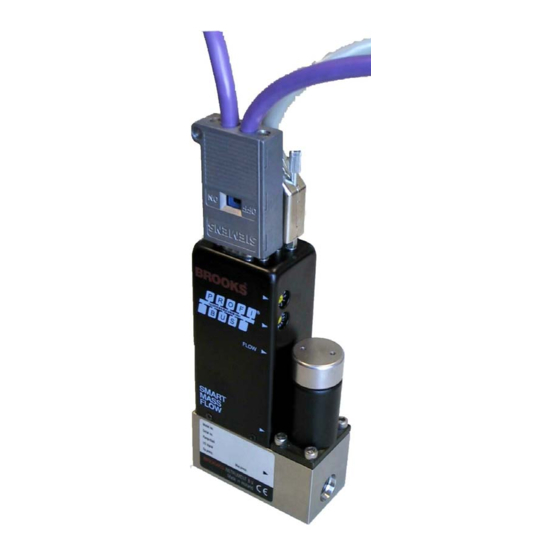
The slave address can be 126 at maximum since 127 is the Global Station Address. On the Profibus interface piggyback for the Brooks Smart TMF devices, the station address selection is implemented by two rotary switches, located on the side of the device (location of the valve), refer to Figure 3-5 below. -
Page 19: Zero Pushbutton
The zero pushbutton is located on the opposite side of the Profibus-DP address selector switches on the Brooks Smart TMF device. To achieve a valid (re)-bal- ance of the flow sensor, take the following actions: 1. Make sure the device has been fully warmed up after power-up, i.e. it should be powered up for at least 45 minutes. -
Page 20: Profibus Network Wiring
Brooks Smart TMF series device to lock on to this baud rate after an automatic search for it. Also, if no valid messages have been detected on the network after a pre-programmed time out, the Brooks Smart TMF series will switch to baud search mode, and search for the correct baud rate until found. -
Page 21: Line Termination Requirements
Figure 3-6: Profibus line termination configuration. The Brooks Smart TMF series does not provide internal termination resistors. Therefore, if required at the connector of a Smart TMF series device (e.g. -
Page 22: Figure 3-8: High-Speed Communication Inductors
Installation and Operation Manual X-DPT-Profibus-DP-Interface-eng PN 541-C-068-AAG November, 2008 In order to prevent these effects special precautions must be taken. A special connection plug combination is required, including two serially placed inductors each one in each network line. It is recommended that the inductors be placed in the connector rather than in the Profibus device. -
Page 23: Slave Configuration
1. BIMF5801.GSD - Smart Mass Flow Controllers (MFC) 2. BIMF5861.GSD - Smart Mass Flow Meters (MFM) and can be found on the www.profibus.com web site or requested at your Brooks Sales representative. ILLUSTRATION OF THE PROFIBUS-DP COMMUNICATION PROCEDURE Power up and/or reboot of master... - Page 24 PN 541-C-068-AAG November, 2008 The user can make the selections as listed in the next section using a configurator program and the files provided. The Brooks Smart Mass Flow Controller is classified as a compact device. Byte Mass Flow Controller...
- Page 25 Installation and Operation Manual X-DPT-Profibus-Interface-eng PN 541-C-068-AAG November, 2008 Mass Flow Controller byte type range default options description [dec] [dec] byte n.a. Internal system parameter n.a. reserved byte 1..10 Select gas calibration 1 = curve 1 Select gas calibration curve 2 = curve 2 3 = curve 3 4 = curve 4...
- Page 26 Installation and Operation Manual X-DPT-Profibus-DP-Interface-eng PN 541-C-068-AAG November, 2008 byte 1...200 Select softstart ramp-up and ramp-down speed 1…200 = %/s Percent per second byte 0..24 Select flow unit 0 = % Percent of full scale 1 = ml/sec Milliliter per second 2 = ml/min Milliliter per minute 3 = ml/hr...
- Page 27 Installation and Operation Manual X-DPT-Profibus-Interface-eng PN 541-C-068-AAG November, 2008 byte 0..2 Select adaptive control option 0 = Off 1 = Tune offset 2 = Tune offset & span byte n.a. Extended user parameter n.a. reserved Mass Flow Meter byte type Range default options...
- Page 28 Installation and Operation Manual X-DPT-Profibus-DP-Interface-eng PN 541-C-068-AAG November, 2008 byte n.a. Not used n.a. reserved byte 0..24 Select flow unit 0 = % Percent of full scale 1 = ml/sec Milliliter per second 2 = ml/min Milliliter per minute 3 = ml/hr Milliliter per hour 4 = l/sec Liter per second...
-
Page 29: Configuration Of The Slave
The entry takes place via identifier bytes. A configuration telegram can contain one or more identifiers. In case of the Brooks Mass Flow products the special identifier format is used. This first code indicates one byte of output data length follows, one byte of input data length follows and one byte of manufacturer specific data. - Page 30 Installation and Operation Manual X-DPT-Profibus-DP-Interface-eng PN 541-C-068-AAG November, 2008 For module 3: Byte Code Description 0xC1 Special identifier with one length byte each for Output and Input follows, with one byte of vendor specific data 0x84 Output data, 5 bytes (1 float + 1 byte) 0x94 Input data, 21 bytes (4 floats + 1 unsigned integer + 1 byte) 0x03...
-
Page 31: Diagnostic
Installation and Operation Manual X-DPT-Profibus-Interface-eng PN 541-C-068-AAG November, 2008 4.5 DIAGNOSTIC 4.5.1 Device diagnostic Message Any Smart TMF series device features extensive diagnostics capabilities. Access to this information is provided through the Profibus-DP defined diagnostics mes- sage. In the start-up state, when connected to the network and prior to entering the data exchange state, the device will generate two diagnostic messages: one right after power up to notify the master of its presence on the network, and one after successful configuration check, to notify the master that the system is ready for... -
Page 32: Fatal System Errors
Installation and Operation Manual X-DPT-Profibus-DP-Interface-eng PN 541-C-068-AAG November, 2008 Explanation of error bits: 1. Invalid EEPROM command: The code send to the slave device with command byte 1 is invalid. i.e. the two least significant bits of the first command byte have both been set to 1. 2. -
Page 33: Table 5-4: Diagnostics: Primary Non-Fatal System Error/Alarm Bits
Installation and Operation Manual X-DPT-Profibus-Interface-eng PN 541-C-068-AAG November, 2008 4. EEPROM error: During operation the backup parameter database, located in EEPROM is continuously checked by comparing the contents of each parameter in the operational database (including the checksum) with the contents of the backup database. -
Page 34: Secondary Non-Fatal System Errors
Installation and Operation Manual X-DPT-Profibus-DP-Interface-eng PN 541-C-068-AAG November, 2008 4.5.5 Secondary non-fatal system errors Table 5-5 below shows the bit-mapped alarm bits of the fourth extended diag- nostics byte, the secondary non-fatal system errors. These error bits all indi- cate a secondary non-fatal system alarm, non-hardware related. At the occur- rence of one or more of these alarms the device will continue to operate as best as possible. -
Page 35: Data Exchange Mode
Installation and Operation Manual X-DPT-Profibus-Interface-eng PN 541-C-068-AAG November, 2008 Explanation of error/alarm bits: 1. Temperature too high error: If the ambient temperature exceeds the device’s maximum operating temperature, this alarm will be set. It will disappear if the temperature drops below the maximum operating tempera- ture again. - Page 36 Installation and Operation Manual X-DPT-Profibus-DP-Interface-eng PN 541-C-068-AAG November, 2008 I/O memory map MFC, Mass Flow Controller bimf5801.gsd module 1: “out[Setp],in[Flow]” description byte # byte size type Output Setp setpoint 0…..3 floating point description byte # byte size type Input Flow flow 0…..3 floating point...
- Page 37 Installation and Operation Manual X-DPT-Profibus-Interface-eng PN 541-C-068-AAG November, 2008 In the following table the functionality of this command byte is shown. Although it is one byte with two functions, totalizer and valve override, this byte is representing two nibbles (4 bits): •...
-
Page 38: Example Of The Profibus-Dp Communication Procedure
Installation and Operation Manual X-DPT-Profibus-DP-Interface-eng PN 541-C-068-AAG November, 2008 For STEP7 (Siemens) the following routines can be used: SFC14, DPRD_DAT, read consistent data of a standard DP slave. SFC15, DPRW_DAT, write consistent data to a standard DP slave. Please, consult the manufacturer of your master device for all detailed informa- tion about consistent data exchange. -
Page 39: Modellisting
Installation and Operation Manual X-DPT-Profibus-Interface-eng PN 541-C-068-AAG November, 2008 Modellisting Model 58.. Series BROOKS SMART MASS FLOW PRODUCTS SMART MASS FLOW METERS / CONTROLLERS BASE MODEL NUMBER DESCRIPTION 5860S/BA MASS FLOW METER; F.S. FLOWRANGES: 0.003 - 0.008 ln/min. 5860S/BC MASS FLOW METER; F.S. FLOWRANGES: 0.008 - 30 ln/min. - Page 40 VCO (200 ln/min. max.) (ONLY FOR 5850/60/51/61/53/63) 3/4" (ONLY FOR 5853/63) ½" VCR (200 ln/min. max.) (ONLY FOR 5850/60/51/61/53/63) BROOKS SMART MASS FLOW PRODUCTS SMART MASS FLOW METERS / CONTROLLERS BASE MODEL NUMBER DESCRIPTION MECHANICAL CONNECTIONS DN15PN40 (ONLY FOR 5853/63)
- Page 41 Installation and Operation Manual X-DPT-Profibus-Interface-eng PN 541-C-068-AAG November, 2008 BROOKS SMART MASS FLOW PRODUCTS SMART MASS FLOW METERS / CONTROLLERS BASE MODEL NUMBER DESCRIPTION ELECTRICAL INPUT/OUTPUT INPUT OUTPUT 0-5Vdc 0-5 Vdc & 0-20mA (INCL. RS 232, 9600 BDS) 4-20mA 4-20 mA & 1-5Vdc (INCL.
- Page 42 + 24 Vdc = (Standard selection) + 15 Vdc only SPECIFY AREA CLASSIFICATION 1 SAFE AREA 2 CERTIFIED FOR USE IN ZONE 2 9 SPECIFY 5850S/BC 1H A 1 A B3 C A 1 B 1 = TYPICAL MODEL NUMBER...
- Page 43 Installation and Operation Manual X-DPT-Profibus-Interface-eng PN 541-C-068-AAG November, 2008 Modellisting Model MF Series BROOKS MF-SERIES SMART MASS FLOW METERS / CONTROLLERS BASE MODEL NUMBER DESCRIPTION MF60S/AA MASS FLOW METER; F.S. FLOWRANGES: 0.003 - 0.008 ln/min. MF60S/AC MASS FLOW METER; F.S. FLOWRANGES: 0.008 - 30 ln/min.
- Page 44 ½" VCO (200 ln/min. max.) (ONLY FOR 5850/60/51/61/53/63) 3/4" (ONLY FOR 5853/63) ½" VCR (200 ln/min. max.) (ONLY FOR 5850/60/51/61/53/63) BROOKS MF-SERIES SMART MASS FLOW METERS / CONTROLLERS BASE MODEL NUMBER DESCRIPTION MECHANICAL CONNECTIONS DN15PN40 (ONLY FOR MF53/63) DN25PN40 (ONLY FOR MF53/63)
- Page 45 (NO VALVE) NORMALLY CLOSED (MF5850/51 SERIES) NORMALLY CLOSED (PRESS.DIFF. >2BAR. MF5853 SERIES) NORMALLY CLOSED (PRESS.DIFF. <2BAR. MF5853 SERIES) NORMALLY OPENED (MF5850 ONLY) SPECIFY BROOKS MF-SERIES SMART MASS FLOW METERS / CONTROLLERS BASE MODEL NUMBER DESCRIPTION ELECTRICAL INPUT/OUTPUT INPUT OUTPUT 0-5Vdc 0-5 Vdc &...
- Page 46 Installation and Operation Manual X-DPT-Profibus-DP-Interface-eng PN 541-C-068-AAG November, 2008 ELECTRICAL CONNECTION PG11 CABLE GLAND 1/2" NPT ADAPTER CONDUIT ENTRY SPECIFY ENHANCEMENTS STANDARD RESPONSE:< 1 SEC (5850/51) < 3 SEC (5853) [1]. FAST RESPONSE (SPECIFY VALUES ..SEC.) [1] LINEAR RAMP (SPECIFY VALUES ..%/SEC.) [1] FLOW OUTPUT DAMPING (SPECIFY VALUES ..
-
Page 47: Appendix A Profibus-Dp Message Services
Installation and Operation Manual X-DPT-Profibus-Interface-eng PN 541-C-068-AAG November, 2008 Appendix A PROFIBUS-DP message services Global control commands The Profibus standard provides the possibility to issue global command to one or more slave devices. These commands are pre-defined bit mapped commands in the global command data byte, and both the Smart Mass Flow Meter and Con- troller models will support two of these commands. - Page 48 Installation and Operation Manual X-DPT-Profibus-DP-Interface-eng PN 541-C-068-AAG November, 2008 For a Smart Mass Flow Meter this command only applies to the command byte (if enabled). The sync/unsync feature allows (e.g.) an application start or stop a number of totalizers at the same time. E.g.
-
Page 49: Appendix B Ieee 754 Floating Point Format
Installation and Operation Manual X-DPT-Profibus-Interface-eng PN 541-C-068-AAG November, 2008 Appendix B IEEE 754 Floating Point Format Our products uses in most cases floating points as input and output parameters. These floating points are defined as IEEE 754 32-bit single precision types. This means that each parameter of a floating point type uses four hexadecimal bytes. - Page 50 BROOKS SERVICE AND SUPPORT Brooks is committed to assuring all of our customers receive the ideal flow solution for their application, along with outstanding service and support to back it up. We operate first class repair facilities located around the world to provide rapid response and support.
Need help?
Do you have a question about the 5850S and is the answer not in the manual?
Questions and answers