
Related Manuals for Brooks Smart Series


Summary of Contents for Brooks Smart Series
- Page 1 (217) 352-9330 | Click HERE Find the Brooks Instrument 5851S at our website:...
- Page 2 Installation and Operation Manual X-TMF-5800S-MFC-eng PN 541-C-051-AAG Models 5800-S November, 2008 ® Brooks Smart-Series Digital Mass Flow Meters and Controllers Brooks Smart Family Artisan Technology Group - Quality Instrumentation ... Guaranteed | (888) 88-SOURCE | www.artisantg.com...
- Page 3 Read this page before proceeding! Brooks Instrument designs, manufactures and tests its products to meet many national and international standards. Because these instruments are sophisticated technical products, you must properly install, use and maintain them to ensure they continue to operate within their normal specifications.
- Page 4 We appreciate this opportunity to service your flow measurement and control requirements with a Brooks Instrument device. Every day, flow customers all over the world turn to Brooks Instrument for solutions to their gas and liquid low-flow applications. Brooks provides an array of flow measurement and control products for various industries from biopharmaceuticals, oil and gas, fuel cell research and chemicals, to medical devices, analytical instrumentation, semiconductor manufacturing, and more.
-
Page 5: Table Of Contents
Installation and Operation Manual X-TMF-5800S-MFC-eng PN 541-C-051-AAG Models 5800-S November, 2008 Table of Contents Section 1:Introduction ............................5 1.1 Purpose ............................5 1.2 How to use this Manual ........................5 1.3 Description ............................6 Section 2: Installation ............................9 2.1 General ............................9 2.2 Receipt of Equipment ........................ -
Page 6: Section 1:Introduction
1.1 Purpose This instruction manual is intended to provide the user with all the information necessary to install, operate and maintain the Brooks Smart series Mass Flow meters 5860S, 5861S, 5863S and controllers 5850S, 5851S, 5853S. 1.2 How to use this Manual It is recommended to read this manual before installing, operating or repairing these Mass Flow Instruments. -
Page 7: Description
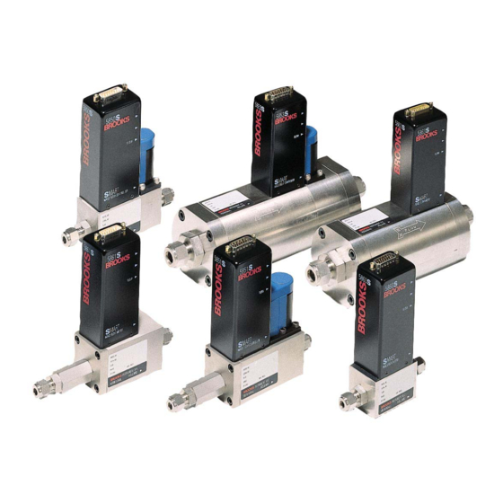
Document: Brooks part number: 541-C-053-AAA. 1.3 Description Models 5860S, 5861S, 5863S and 5864S Brooks Smart Mass Flow Meters are primarily used to provide accurate measurements of gas flows. The heart of these systems is the thermal mass flow sensor, which produces an electrical output signal as a function of flow rate. - Page 8 Installation and Operation Manual Section 1: Introduction X-TMF-5800S-MFC-eng PN 541-C-051-AAG Models 5800-S November, 2008 • Output damping provides a constant scale reading under fluctuating flow rate conditions. Standard factory setting: 0.5 sec. • Output limiting prevents possible damage to delicate acquisition devices by limiting the output to 0-5.25 Vdc on the voltage signal output and 0-21 mA on the current output.
- Page 9 Section 1: Introduction Installation and Operation Manual X-TMF-5800S-MFC-eng PN 541-C-051-AAG Models 5800-S November, 2008 • selectable soft start • adaptive valve control ⇒ Adaptive filtering for signal flow component • Alarms ⇒ Self-diagnostic • EEPROM error • database error • analogue output error ⇒...
-
Page 10: Section 2: Installation
If the packing case is damaged, the local carrier should be notified at once regarding his liability. A report should be submitted to your nearest Product Service Department. Brooks Instrument 407 W. Vine Street P.O. Box 903... -
Page 11: Recommended Storage Practice
Models 5800-S November, 2008 2.3 Recommended Storage Practice If equipment supplied by Brooks Instrument is to be placed in intermediate or long-term storage, it is recommended that it be: a. Stored within the original shipping container. b. Stored in a sheltered area, under the following conditions: 1) Optimum ambient temperature 21°C (70 °F), maximum 32 °C (90 °F),... -
Page 12: Mechanical Installation
Installation and Operation Manual Section 2: Installation X-TMF-5800S-MFC-eng PN 541-C-051-AAG Models 5800-S November, 2008 2.6 Mechanical Installation (For dimensional drawings see Appendix B: Dimensional drawings) NOTE: When installing the Mass Flow device, care should be taken to prevent foreign materials from entering the instrument’s inlet or outlet. Do not remove the protective end-caps until the actual moment of installation. -
Page 13: Electrical Interfacing
Section 2: Installation Installation and Operation Manual X-TMF-5800S-MFC-eng PN 541-C-051-AAG Models 5800-S November, 2008 2.8 Electrical Interfacing The installation of Smart TMF includes a 15-pin Sub-D connector. For details of correct installation, see Table 2-1 Table 2-1: Electrical interfacing. Smart TMF Pin (TMF side) Function Controller... -
Page 14: Figure 2-1: Open Collector
Installation and Operation Manual Section 2: Installation X-TMF-5800S-MFC-eng PN 541-C-051-AAG Models 5800-S November, 2008 common) on the D-connector. If a -15 Vdc power supply is required, pin 6 must be connected and jumper [K2] on the p.c. board must be set the lower position (see Figure 2-2). -
Page 15: Digital Communication
NOTE: The printed circuit boards only need to be reconfigured if the hardware settings differ from those specified at the time of ordering. Brooks Smart Mass Flow Meters and Controllers incorporate two printed circuit boards: one main board containing the processor and a piggyback board. -
Page 16: Table 2-2: Dipswitch Settings
RxD the input signal.The communication terminals can be directly connected to a serial COM-port of any PC. The other part of the terminals can be connected to Brooks model 0152/0154 Microprocessor-based Read-out and Control Electronics. This model provides the power supply for Smart Mass Flow devices, as well as providing local read-out and displaying the analogue output signals. -
Page 17: Interconnection
If no digital communication is required (i.e. analogue I/O only), the following cables are available for connection of the Smart Mass Flow Meter/Controller to the Brooks Microprocessor Control & Read-out Unit (see figure 2-5): Artisan Technology Group - Quality Instrumentation ... Guaranteed | (888) 88-SOURCE | www.artisantg.com... -
Page 18: Figure 2-5: Tmf/C To Read-Out Cable
Figure 2-5: TMF/C to Read-out cable If no digital communication is required, a split cable can be supplied to interconnect the Brooks Microprocessor Control & Read-out Unit, the Smart Mass Flow Meter/Controller and computer (see figure 2-5): Length: 3 m;... -
Page 19: Table 2-3: Electrical Interfacing. Smart Tmf Cable
Section 2: Installation Installation and Operation Manual X-TMF-5800S-MFC-eng PN 541-C-051-AAG Models 5800-S November, 2008 Table 2-3: Electrical interfacing. Smart TMF cable Sub-D (15 c.) Read-out side Computer side Colour Function sub D (15p) sub D (15p) sub D (25p) sub D (9p) female male female... -
Page 20: Section 3: Operation
3.3 Calibration Procedure Calibration of the Smart Mass Flow device is not described in this manual. Calibration can only be achieved with use of the accurate Brooks Vol-U-Meter equipment and the digital communication. Artisan Technology Group - Quality Instrumentation ... Guaranteed | (888) 88-SOURCE | www.artisantg.com... -
Page 21: Section 4: Maintenance
Installation and Operation Manual X-TMF-5800S-MFC-eng PN 541-C-051-AAG Models 5800-S November, 2008 Section 4: Maintenance 4.1 General No routine maintenance is required on the Smart Mass Flow Meters and Controllers other than occasional cleaning. The in-line filter should periodically be replaced or ultrasonically cleaned. NOTE: If recalibration is required, but the necessary expertise or equipment is not available, the instrument should be returned to the factory. - Page 22 November, 2008 necessary, perform the zero adjustment procedure (section 3.2). If the output signal does not zero properly, please contact Brooks Instrument. 2. Connect the instrument to a source of the same gas used for its original calibration. Regulate the Set point to 100% flow and adjust the inlet and outlet pressures to the calibration conditions.
-
Page 23: Table 4-1: Troubleshooting
Valve override input is Check the valve override input grounded (pin 12) Defective electronic board Contact Brooks Instrument. Output signal stays at approx. Valve leaks or is stuck Clean and/or adjust control valve 5.25 Vdc or 21 mA (regardless open (applicable to MFC) (Section 4.3). -
Page 24: Cleaning Procedures
Such calibration requires the use of accurate and traceable calibration equipment such as Brooks Volumeter equipment, in addition to digital communications. However, if the above equipment is available at your facility, then Brooks Instrument will supply you with copy of the calibration procedure document (no.:834-P-064) upon request. -
Page 25: Section 5: Specification
Installation and Operation Manual X-TMF-5800S-MFC-eng PN 541-C-051-AAG Models 5800-S November, 2008 Section 5: Specification PERFORMANCE SPECIFICATIONS Flow ± 0.7% of rate and ±0.2% F.S. (at calibration conditions) Accuracy ± 0.5% of rate and ±0.1% F.S. (optional consult factory) ± 1.0% F.S. for flowrates above 1100 l /min (for 5863/5853) Repeatability ±... -
Page 26: Table 5-1: Flow Ranges And Pressure Ratings
"unauthorized" setting or reranging of span or zero, these functions are only accessible via the Brooks Smart Control, model 0160, or using Smart DDE, model 0162. Power +15Vdc to +28Vdc or +/-15Vdc. (use only 24 Vdc for NO requirements valves and for use of 5851 S). - Page 27 Section 5: Specification Installation and Operation Manual X-TMF-5800S-MFC-eng PN 541-C-051-AAG Models 5800-S November, 2008 Temperature Both ambient and process gas: 0-70 °C. Leak Integrity Outboard: 1 x 10 mbar l/sec. Helium Warm-up time < 10 minutes; 1% F.S. accuracy. Performance within specifications: 45 minutes. Damping Damping from 0 to 10 seconds is possible for the flow output signal(s) * (default setting is 0.5 sec.).
- Page 28 Installation and Operation Manual Section 5: Specification X-TMF-5800S-MFC-eng PN 541-C-051-AAG Models 5800-S November, 2008 Artisan Technology Group - Quality Instrumentation ... Guaranteed | (888) 88-SOURCE | www.artisantg.com...
-
Page 29: Appendix A: Gas Conversion Tables
This scale shift can be calculated by using the ratio of the molar specific heat of the two gases, or the sensor conversion factor. The gasconversion table is available at Brooks Instrument under document no.: J-836-D-508. USE OF A MFC/M FOR A DIFFERENT GAS THAN IT IS CALIBRATED FOR: For use with a different gas type, multiply the output reading by the ratio of the gas factor of the desired gas and the gas factor of the calibrated gas. - Page 30 Installation and Operation Manual Appendix A X-TMF-5800S-MFC-eng PN 541-C-051-AAG Models 5800-S November, 2008 Gas Conversion Table Gasname Formula Gasfactor Orifice factor Density (kg/m3) Acetylene (Ethyne) C2H2 0,615 0,97 1,173 Mixture 0,998 1,018 1,293 Allene C3H4 0,478 1,199 1,787 Ammonia 0,786 0,781 0,771 Argon...
- Page 31 Appendix A Installation and Operation Manual X-TMF-5800S-MFC-eng PN 541-C-051-AAG Models 5800-S November, 2008 Gas Conversion Table (continued) Dimethylamine (CH3)2NH 0,37 1,269 2,013 Dimethylether (CH3)2O 0,392 1,281 2,055 2,2-Dimethylpropane C(CH3)4 0,247 1,613 3,244 Disilane Si2H6 0,332 1,493 2,779 Ethane C2H6 0,49 1,038 1,357 Ethanol...
- Page 32 Installation and Operation Manual Appendix A X-TMF-5800S-MFC-eng PN 541-C-051-AAG Models 5800-S November, 2008 Gas Conversion Table (continued) Nitrogen Dioxide 0,758 1,713 2,052 Nitrogen Trifluoride 0,501 1,598 3,168 Nitrogen Trioxide N2O3 0,443 1,649 3,389 Nitrosyl Chloride NOCL 0,644 1,529 2,913 Nitrous Oxide 0,752 1,259 1,964...
-
Page 33: Appendix B: Dimensional Drawings
Installation and Operation Manual X-TMF-5800S-MFC-eng PN 541-C-051-AAG Models 5800-S November, 2008 Appendix B: Dimensional drawings Model 5860S Model 5861S 5 8 6 1 S CO NNECTIO NS A ( mm) In c h e s Filte r s >> e x c l. in c l. - Page 34 Installation and Operation Manual Appendix B X-TMF-5800S-MFC-eng PN 541-C-051-AAG Models 5800-S November, 2008 Model 5850S Model 5851S 5851S CONNECTIONS A (mm) Inc hes Filters >> ex c l. inc l. ex c l. inc l. 5850S CONNECTIONS A (mm) Inches 9/16-18 UNF (no 3,68 9/16-18 UNF (no adapters)
-
Page 35: Appendix C:translation Of Ce Marking Electrical Installation Instructions
Dansk Brooks Instrument har gennemført CE mærkning af elektronisk udstyr med succes, i henhold til regulativet om elektrisk støj (EMC direktivet 89/336/EEC). Der skal dog gøres opmærksom på benyttelsen af signalkabler i forbindelse med CE mærkede udstyr. - Page 36 November, 2008 Español Los equipos de Brooks (eléctricos/electrónicos) en relación con la marca CE han pasado satisfactoriamente las pruebas referentes a las regulaciones de Compatibilidad Electro magnetica (EMC directiva 89/336/EEC). Sin embargo se requiere una atención especial en el momento de seleccionar el cable de señal cuando se va a utilizar un equipo con marca Calidad del cable de señal, prensaestopas y conectores:...
- Page 37 E’ richiesta comunque una speciale attenzione nella scelta dei cavi di segnale da usarsi con la strumentazione soggetta a marchio CE. Qualità dei cavi di segnale e dei relativi connettori: Brooks fornisce cavi di elevata qualità che soddisfano le specifiche richieste dalla certificazione CE. Se l’utente intende usare propri cavi, questi devono possedere una schermatura del 80%.
- Page 38 November, 2008 Nederlands Alle CE gemarkeerde elektrische en elektronische produkten van Brooks Instrument zijn met succes getest en voldoen aan de wetgeving voor Electro Magnetische Compatibiliteit (EMC wetgeving volgens 89/336/EEC). Speciale aandacht is echter vereist wanneer de signaalkabel gekozen wordt voor gebruik met CE gemarkeerde produkten.
- Page 39 Suoja on oltava maadoitettu. Svensk Brooks (elektriska / elektronik) utrustning, som är CE-märkt, har testats och godkänts enligt gällande regler för elektromagnetisk kompabilitet (EMC direktiv 89/336/EEC). Speciell hänsyn måste emellertid tas vid val av signalkabel som ska användas tillsammans med CE-märkt utrustning.
-
Page 40: Appendix D: Important Safety Instructions
Please make sure that the process line pressure is removed prior to service. Please make sure that original parts of Brooks are used when the device requires servicing. Note however that look- alike substitutions and procedures can affect the product’s performance and place the save operation of your process at risk. - Page 41 Overtuig u zelf ervan dat de procesdruk is afgevoerd alvorens onderhoud aan het instrument te plegen. Overtuig u ervan dat er uitsluitend originele Brooks Instrument onderdelen worden gebruikt voor onderhoud en service aan het instrument. U wordt erop gewezen dat het gebruik van universele onderdelen en voorschriften om daar mee om te gaan, nadelige gevolgen kunnen hebben voor het gebruik van het instrument, en daardoor de juiste weking van uw proces in gevaar kan komen.
- Page 42 Dieser Anhang enthält wichtige Hinweise für einen sicheren Betrieb des Ganzmetall-Schwebekörperdurchflussmessers der Baureihe Thermal Mass Flow Meter / Controller Series von Brooks Instrument . Das Gerät entspricht den gültigen PED- Richtlinien (PRESSURE EQUIPMENT CE DIRECTIVE 97/23/EC). Konsultieren Sie lokale Zulassungsbehörden für nationale und/oder regionale Sicherheitsbestimmungen bzw.
- Page 43 Påse at prosesstrykket er avlastet før utstyret demonteres. Bruk alltid Brooks original deler ved service. Merk at selv om erstatningene ser like ut kan de påvirke produktets virkemåte og gjøre prosessen usikker. Det kan videre føre til brann, elektrisk risiko eller feil virkemåte.
- Page 44 Este apéndice contiene importantes instrucciones de operación y seguridad para el uso de los rotámetros de tubo de vidrio BROOKS de la Thermal Mass Flow Meter / Controller. El instrumento es conforme a la directiva 97/23/CE sobre Equipos a Presión de la Comunidad Europea (PED). Consulte con sus autoridades locales por si existieran normas ó...
-
Page 45: Appendix E: Modellist
Installation and Operation Manual X-TMF-5800S-MFC-eng PN 541-C-051-AAG Models 5800-S November, 2008 Appendix E: Modellist BROOKS SMART MASS FLOW PRODUCTS SMART MASS FLOW METERS / CONTROLLERS BASE M ODEL NUM BER DESCRIPTION 5860S/BA MA SS FLOW METER; F.S. FLOWRA NGES: 0.003 - 0.008 ln/min. - Page 46 Installation and Operation Manual Appendix E X-TMF-5800S-MFC-eng PN 541-C-051-AAG Models 5800-S November, 2008 M ECHANICAL CONNECTIONS WITHOUT A DA PTORS (9/16"-18" UNF) (ONLY FOR 5850/60/51/61/53/63) 1/4" TUBE COMPRESSION FITTINGS (ONLY FOR 5850/60/51/61) 1/8" TUBE COMPRESSION FITTINGS (ONLY FOR 5850/60/51/61) 3/8" TUBE COMPRESSION FITTINGS (ONLY FOR 5851/61) 1/4"...
- Page 47 Appendix E Installation and Operation Manual X-TMF-5800S-MFC-eng PN 541-C-051-AAG Models 5800-S November, 2008 V ALV E TYPE METER ONLY (NO V A LV E) NORMA LLY CLOSED (5850/51 SERIES) NORMA LLY CLOSED (PRESS.DIFF. >2BA R. 5853 SERIES) NORMA LLY CLOSED (PRESS.DIFF. <2BA R. 5853 SERIES) NORMA LLY OPENED (5850 ONLY ) NORMA LLY CLOSED, 5850 SERIES, 300 BA R...
- Page 48 2 CERTIFIED FOR USE IN ZONE 2 9 SPECIFY 5850S/BC 1H A 1 A B3 C A 1 B 1 = TYPICAL M ODEL NUM BER BROOKS SMART MASS FLOW PRODUCTS SMART MASS FLOW METERS / CONTROLLERS NOTES: ENHANCEMENTS PLEASE FILL IN THE REQUESTED SPECIFICATIONS WHEN YOU HAVE DESCRIBED THE ENHANCEMENTS.
- Page 49 Appendix E Installation and Operation Manual X-TMF-5800S-MFC-eng PN 541-C-051-AAG Models 5800-S November, 2008 OPTIONS A) HIGH PRESSURE RATING 300 BAR FOR MODEL 5861S B) FOR GASES WHICH CLOG AND CONTAMINATE THE MFC EASILY, AN ANTI-CLOG LAMINAR FLOW ELEMENT MUST BE ORDERED. FOR FLOW RANGES UP TO 3460 mln/min. N2, ADD: C) 0 - 10 Vdc I/O CONFIGURATION (NO FURTHER I/O OPTIONS ARE POSSIBLE WITH THIS SELECTION) D) 0 - 5 Vdc Input / 0 - 10 Vdc output (0550E replacement configuration) E) DIN/ANSI (PN40/150 LBS PRESSURE RATING) FLANGED CONNECTION FOR THE 1,5"...
- Page 50 Installation and Operation Manual X-TMF-5800S-MFC-eng PN 541-C-051-AAG Models 5800-S November, 2008 THIS PAGE WAS INTENTIONALLY LEFT BLANK Artisan Technology Group - Quality Instrumentation ... Guaranteed | (888) 88-SOURCE | www.artisantg.com...
- Page 51 BROOKS SERVICE AND SUPPORT Brooks is committed to assuring all of our customers receive the ideal flow solution for their application, along with outstanding service and support to back it up. We operate first class repair facilities located around the world to provide rapid response and support.
Need help?
Do you have a question about the Smart Series and is the answer not in the manual?
Questions and answers