Table of Contents
Advertisement
Quick Links
Advertisement
Table of Contents

Related Manuals for DFI CS632


Summary of Contents for DFI CS632
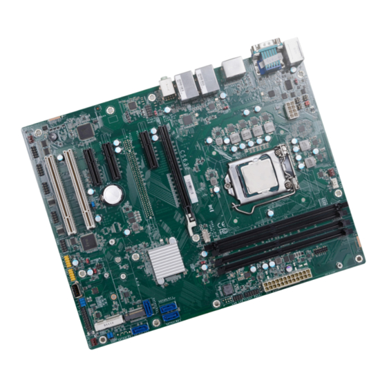
- Page 1 CS632-C246/Q370 ATX Industrial Motherboard User’s Manual A-531-M-2007...
- Page 2 1. The changes or modifications not expressly approved by the party responsible for com- pliance could void the user’s authority to operate the equipment. 2. Shielded interface cables must be used in order to comply with the emission limits. User's Manual | CS632...
-
Page 3: Table Of Contents
Intel Serial IO Drivers ......................74 LPC ..........................29 Intel Rapid Storage Technology ..................75 External COM port Module ...................29 Adobe Acrobat Reader 9.3 ....................77 LAN LED .........................30 Expansion Slots ......................30 Installing the M.2 Module .....................31 Installing the Mini PCIe Module ...................32 User's Manual | CS632... - Page 4 • To reduce the risk of electric shock, unplug the power cord before removing the sys- tem chassis cover for installation or servicing. After installation or servicing, cover the system chassis before plugging the power cord. User's Manual | CS632...
- Page 5 This may differ in accordance with the sales region or models in which it was sold. For more information about the standard package in your region, please contact your dealer or sales representative. Before Using the System Board User's Manual | CS632...
- Page 6 Storage: 5 to 90% RH 1 x Mini PCIe (PCIe/mSATA, share w/SATA conn. as opt./USB2.0) MECHANICAL Dimensions ATX Form Factor: 305mm (12") x 244mm (9.6") 1 x M.2 2242/2280 M key (PCIe x4 NVMe, Intel Optane Memory Support) User's Manual | CS632...
-
Page 7: Chapter 1 - Introduction
ATX Form Factor: 305mm (12") x 244mm (9.6") AUDIO Audio Codec Realtek ALC887 (ALC888 as opt.) ® ETHERNET Controller 1 x Intel I210AT PCIe (10/100/1000Mbps) 1 x Intel ® I219LM PCIe with iAMT12.0 (10/100/1000Mbps) (only Core i7/i5 supports iAMT) User's Manual | CS632... -
Page 8: Cs632-Q370
Event) signal. However, if your system is in the Suspend mode, you can power-on the system only through an IRQ or DMA interrupt. Wake-On-USB This function allows you to use a USB keyboard or USB mouse to wake up a system from the S3 (STR - Suspend To RAM) state. User's Manual | CS632... -
Page 9: Chapter 2 - Hardware Installation
Failure to do so will cause se- vere damage to the motherboard and components. System COM2 COM3 COM4 COM5 COM6 Digital I/O System Fan 3 Fan 2 9/10 11/12 USB 2.0 User's Manual | CS632... -
Page 10: System Memory
Dual Channel DIMMs of the same memory configuration are on different channels. Step 1 Features • CS632-C246: Four 288-pin ECC/Non-ECC DIMM up to 64GB • CS632-Q370: Four 288-pin Non-ECC DIMM up to 64GB • Dual Channel DDR4 2400/2666 MHz Step 2... -
Page 11: Removing The Dimm Module
The tabs snap automatically to the edges of the card and lock the card in place. S ocket Side View Socket Side View Step 1 Step 1 Step 1 Step 1 Step 2 Step 2 Step 2 Step 2 Step 3 Step 3 Step 3 Step 3 User's Manual | CS632... -
Page 12: Cpu
These illustrations and photos are for reference only. 4. Unlock the socket by pressing the load lever down, moving it sideways until to escape the retention tab. Lift the load lever up when it’s released. Load lever Retention tab User's Manual | CS632... - Page 13 Important: 9. Press down the load The CPU will fit in only one orientation and can easily be seated without exerting lever and hook it under any force. the retention tab. User's Manual | CS632...
-
Page 14: Installing The Fan And Heat Sink
5. Connect the CPU fan’s cable to the CPU fan connector on the system board. 3. Orient the heat sink so that the CPU fan’s cable is nearest the CPU fan connector. CPU fan connector Mounting holes User's Manual | CS632... -
Page 15: Jumper Settings
1 and pin 2. 3. Plug the power cord and power-on the system. JP1 & JP2 „ 1-3, 2-4 On „ 3-5, 4-6 On „ 3-5, 4-6 On „ 1-2 On: Normal (default) „ 2-3 On: Clear CMOS User's Manual | CS632... -
Page 16: Com1 Rs232 Power Select
„ 2-4 On: Pin 1 = DCD- „ 4-6 On: Pin 1 = +12V „ 1-2 On: 3V3DU (default) „ 2-3 On: 3V3 (COM1) „ 1-3 On: Pin 9 = RI- „ 3-5 On: Pin 9 = +5V User's Manual | CS632... -
Page 17: Mini Pcie Signal Select
„ 1-2 On: Mini PCIe (default) „ 2-3 On: mSATA Internal USB 9/10 (USB 2.0) Internal USB 11/12 (USB 2.0) Internal USB 5/6 (USB 3.1 Gen 2) „ 2-3 On: 5V Rear USB 7/8 (USB 2.0) User's Manual | CS632... -
Page 18: Digital I/O (Dio) Power Select
JP18 is used to select for DIO0~DIO3. JP19 is used to select for DIO4~DIO7. „ 1-2 On: +5VDU (default) „ 2-3 On: +5V „ 1-2 On: DIO power used (default) „ 2-3 On: GND User's Manual | CS632... -
Page 19: Power-On Select
JP11 as listed and illustrated below: „ 1-2 On: Power Button (default) „ 2-3 On: AC In Note: JP11 is an optional feature and may not be present on your motherboard. User's Manual | CS632... -
Page 20: Rear I/O Ports
1 Serial COM port mouse connector. • 1 VGA port • 2 DP++ ports • 2 RJ45 LAN ports • 4 USB 3.1 Gen1 ports • 1 Line-in jack (optional) • 1 Line-out jack • 1 Mic-in jack User's Manual | CS632... -
Page 21: Usb Ports
Install the graphics driver. Refer to the chapter 4 for more information. Wake-On-USB Keyboard/Mouse The Wake-On-USB Keyboard/Mouse function allows you to use a USB keyboard or USB mouse to wake up a system from the S3 (STR - Suspend To RAM) state. User's Manual | CS632... -
Page 22: Rj45 Lan
® Configure the onboard audio port in the Advanced menu (“Audio Configuration” submenu) of the BIOS. Refer to chapter 3 for more information. Driver Installation Install the audio driver. Refer to Chapter 4 for more information. User's Manual | CS632... -
Page 23: Com 1 (Serial) Port
Please refer to the Internal I/O section later in this chapter for more information on Configure the onboard COM ports in the Advanced menu (“Console Redirection” and "SIO NU- the internal COM ports. VOTON6116D" submenus) of the BIOS. Refer to chapter 3 for more information. User's Manual | CS632... -
Page 24: Internal I/O Connectors
The Wake-On-USB Keyboard/Mouse function allows you to use a USB keyboard or USB mouse to wake up a system from the S state(s). Jumper Setting Configure the USB ports' power settings via jumpers as previously instructed in this chapter. User's Manual | CS632... -
Page 25: Front Audio
1. SATA4 and Mini PCIe share one mutual bus and do not co-exist. 2. When SATA0 exists, the M.2 will only support PCIe bus and not mSATA. 3. SATA4 is an optional component and may not be present. User's Manual | CS632... -
Page 26: Digital I/O
Assignment Assignment +12V DIO_7 +12V DIO_6 „ 3-pin Fan Pin Assignment „ 4-pin Fan Pin Assignment DIO_5 Pin Assignment Pin Assignment DIO_4 Ground Ground DIO_3 Power Power DIO_2 +5VDU DIO_1 +5VDU Sense Sense DIO_0 Speed Control User's Manual | CS632... -
Page 27: Power Connector
Insufficient power supplied to the system may result in instability or malfunction of the add-in boards and peripherals. Calculating the system’s approximate power usage is important to ensure that the power supply meets the system’s consump- tion requirements. User's Manual | CS632... -
Page 28: Front Panel
Power On Suspend) state, it will blink at 1-second intervals. When the system is in the S3 (STR - Suspend To RAM) state, it will blink at 4-second intervals. ATX-SW - ATX Power Switch This switch is used to power on or off the system. User's Manual | CS632... -
Page 29: Battery
• There exists explosion hazard if the battery is incorrectly installed. Pin Assignment Pin Assignment • Replace only with the same or equivalent type recommended by the manufacturer. 3V3SB • Dispose of used batteries according to local ordinances. SMBus_Clock SMBus_DATA SMBus_Alert User's Manual | CS632... -
Page 30: Lpc
External COM port Module The LPC connector is used for debugging. The external COM port modules — EXT-RS232 and EXT-RS485 — are designed by DFI’s propri- etary technology, and support four additional COM ports per module. The EXT-RS232/RS485 card is connected to the motherboard via the LPC connector and secured by a standoff as il- lustrated below. -
Page 31: Lan Led
Select the signal of Mini PCIe via jumper settings as previously instructed in this chapter. LINK(LAN2)_1000 LINK(LAN2)_100 LINK(LAN2)_ACTIVITY 3V3DU Note: 1. SATA4 and Mini PCIe share one mutual bus and do not co-exist. 2. When SATA0 exists, the M.2 will not support mSATA. User's Manual | CS632... -
Page 32: Installing The M.2 Module
PCI card only) into the PCI slot. Note: PCIe 1 is by default a x16 bandwidth slot, but can alternatively be x8 bandwidth when PCIe 3 (x8 bandwidth) is present. The option shall be specified prior to pur- chase. User's Manual | CS632... -
Page 33: Installing The Mini Pcie Module
Screw tight the card onto the stand-off with a screw driver and a stand-off screw until the gap between the card and the stand-off closes up. The card should be lying parallel to the board when it’s correctly mounted. User's Manual | CS632... - Page 34 Screw tight the card onto the stand- off with a screw driver and a stand- off screw until the gap between the card and the stand-off closes up. The card should be lying paral- lel to the board when it’s correctly mounted. User's Manual | CS632...
-
Page 35: Chapter 3 - Bios Settings
When “X” appears on the left of a particular field, it indicates that a submenu which contains additional options are available for that field. To display the submenu, move the highlight to that field and press <Enter>. User's Manual | CS632... -
Page 36: Main
The time format is <hour>, <minute>, <second>. The time is based on the 24-hour military-time clock. For example, 1 p.m. is 13:00:00. Hour displays hours from 00 to 23. Minute displays min- utes from 00 to 59. Second displays seconds from 00 to 59. User's Manual | CS632... -
Page 37: Rc Acpi Configuration
The system enter soft-off state after power failure. Power-on signal input is abled, only one thread per enabled core is enabled. required to power up the system. Note: Some of the fields may not be available when the features are not supported by the equipped CPU. User's Manual | CS632... -
Page 38: Power & Performance
Enable or disable CPU Power Management. It allows CPU to enter "C states" when it’s idle and nothing is executing. ME Unconfig on RTC Clear When disabled, ME will not be unconfigured on RTC Clear. Note: The sub-menus are detailed in following sections. User's Manual | CS632... - Page 39 Version 2.20.1271. Copyright (C) 2019 American Megatrends, Inc. USB Provisioning of AMT Secure Erase Mode Enable or disable AMT USB Provisioning. Select Secure Erase module behavior: Simulated or Real. Force Secure Erase Enable or disable Force Secure Erase on next boot. User's Manual | CS632...
- Page 40 This field is used to enable or disable the ME FW Image Re-Flash function, which allows the ration. user to update the ME firmware. Unconfigure ME Enable or disable to unconfigure ME with resetting MEBx password to default. User's Manual | CS632...
-
Page 41: Trusted Computing
Set SuperIO WatchDog Timer Timeout value. The range is from 0 (disabled) to 255. To clear the existing TPM encryption, select "TPM Clear" and restart the system. This field is not available when "Security Device Support" is disabled. Note: The sub-menus are detailed in following sections. User's Manual | CS632... -
Page 42: Nct6116D Hw Monitor
Enable or disable the current serial COM port. Case Open RS485 Auto Flow Enable or disable the case open detection function. Enable or disable RS485 auto flow. This field is only available for COM ports that support RS485 mode. User's Manual | CS632... -
Page 43: Serial Port Console Redirection
▼ SYS Smart Fan/CPU Smart Fan Control = [Disabled] Fix Fan Speed Count Set the fan speed, the value ranging from 1-100%, 100% being full speed. The fans will al- ways operate at the specified speed regardless of gauged temperatures. User's Manual | CS632... -
Page 44: Usb Configuration
Select parity bits: None, Even, Odd, Mark or Space. Stop Bits Select stop bits: 1 bit or 2 bits. Flow Control Select flow control type: None or Hardware RTS/CTS. Flow Control is for RS485 mode and is only supported by Serial Port 1 (COM1). User's Manual | CS632... -
Page 45: Csm Configuration
Set the number of times the presence of media will be checked. Use either +/- or numeric keys to set the value. This field determines OpROM execution policy for devices other than Network, Storage or Video. User's Manual | CS632... -
Page 46: Chipset
Version 2.20.1271. Copyright (C) 2019 American Megatrends, Inc. Primary Display Select which of IGFX/PEG/PCI Graphics device to be the primary display. Internal Graphics Keep IGFX "Enabled" or "Disabled" based on the setup options, or select "Auto" for auto-detec- tion. User's Manual | CS632... -
Page 47: Peg Port Configuration
Enable or disable the root port, or select "Auto" for auto-detection. Enable or disable this field to detect non-compliance PCIe devices in the PEG. Max Link Speed Configure PCIE1/PCIE3 port’s Max Speed: Auto, Gen1, Gen2 or Gen3. User's Manual | CS632... -
Page 48: Pch-Io Configuration
Detect Non-Compliance Device Enable or disable this field to detect non-compliance PCIe devices in the PEG. This field may not appear when the port does not support Non-compliant device detection. Note: The sub-menus are detailed in following sections. User's Manual | CS632... -
Page 49: Sata And Rst Configuration
This field shows up when SATA Mode Selection is set to Intel RST Premium With Intel Optane System Acceleration. Enable or disable to use RST Legacy OROM when CSM is enabled. Port 0/1/2/3/4/ and Hot Plug Enable or disable the Serial ATA port and its hot plug function. User's Manual | CS632... -
Page 50: Security
Secure Boot. Press Enter and a prompt will show up for you to confirm. Reset To Setup Mode Clear the database from the NVRAM, including all the keys and signatures installed in the Key Management menu. Press Enter and a prompt will show up for you to confirm. User's Manual | CS632... -
Page 51: Boot
“Quiet Boot” is set to enabled, “BGRT Logo” will show up for configura- tion. Refer to the Advanced > CSM Configuration for more information. This field will appear only when a USB flash device is detected. Select this field to restore set- ting from the USB flash device. User's Manual | CS632... -
Page 52: Updating The Bios
When the BIOS IC needs to be replaced, you have to populate it properly onto the system board after the EEPROM programmer has been burned and follow the technical person's instructions to confirm that the MAC address should be burned or not. User's Manual | CS632... -
Page 53: Chapter 4 - Intel Amt Settings
FW. →←: Select Screen ↑↓: Select Item Enter: Select +/- : Change Opt. F1: General Help F2: Previous Values F9: Optimized Defaults F10: Save & Exit ESC: Exit Version 2.20.1271. Copyright (C) 2019 American Megatrends, Inc. User's Manual | CS632... -
Page 54: Entering Management Engine Bios Extension (Mebx)
↑↓: Select Item Press <DEL> to enter setup. Enter: Select +/- : Change Opt. F1: General Help F2: Previous Values F9: Optimized Defaults F10: Save & Exit ESC: Exit Version 2.20.1271. Copyright (C) 2019 American Megatrends, Inc. User's Manual | CS632... -
Page 55: Mebx
- At least one 7-bit ASCII non alpha-numeric character, above 0x20, (e.g. !, $, ;); - At least one lower case and one upper case characters. 3. Enter the new password again to verify the new password. Verify password User's Manual | CS632... - Page 56 - At least one 7-bit ASCII non alpha-numeric character, above 0x20, (e.g. !, $, ;); - At least one lower case and one upper case characters. 3. Enter the new password again to verify the new password. Verify password User's Manual | CS632...
-
Page 57: Intel(R) Amt Configuration
> User Consent Password Policy <Anytime> > Network Setup Disabled Activate Network Access Enabled Unconfigure Network Access <Full Unprovision> > Remote Setup And Configuration > Power Control [↑↓] =Move Highlight <Enter> =Complete Entry [Esc] =Discard Changes User's Manual | CS632... - Page 58 Username and Password Select Enabled or Disabled then press Enter. Select Enabled or Disabled then press Enter. Storage Redirection Select Enabled or Disabled then press Enter. KVM Feature Selection Select Enabled or Disabled then press Enter. Disabled Enabled User's Manual | CS632...
- Page 59 User Opt-in the system is being accessed. Select NONE or KVM or ALL then press Enter. NONE Opt-in Configurable from Remote IT Select Enabled or Disabled then press Enter. Disabled Enabled User's Manual | CS632...
- Page 60 > Intel(R) ME Network Name Settings Enter the computer’s domain name and then press Enter. > TCP/IP Settings Computer Domain Name Shared/Dedicated FQDN Select Shared or Dedicated and then press Enter. [↑↓] =Move Highlight [Enter] =Select Entry [Esc] =Exit Dedicated Shared User's Manual | CS632...
- Page 61 TCP/IP SETTINGS > Wired LAN IPV4 Configuration <Enter> =Complete Entry [Esc] =Discard Changes Enter a value for the Time-to-live (TTL) field and then press Enter. Value in Seconds [↑↓] =Move Highlight [Enter] =Select Entry [Esc] =Exit User's Manual | CS632...
- Page 62 0.0.0.0 Default Gateway Address 0.0.0.0 Preferred DNS Address 0.0.0.0 Alternate DNS Address 0.0.0.0 Alternate DNS Address Insert a value from 0.0.0.0 to 255.255.255.255 in IPv4 format. Alternate DNS address 0.0.0.0 <Enter> =Complete Entry [Esc] =Discard Changes User's Manual | CS632...
- Page 63 > Power Control Activates the current network settings > Power Control Full Unprovision and opens the ME network interface Continue: (Y/N) [↑↓] =Move Highlight [Enter] =Select Entry [Esc] =Exit [↑↓] =Move Highlight <Enter> =Complete Entry [Esc] =Discard Changes User's Manual | CS632...
- Page 64 Provisioning Server FQDN > RCFG > TLS PKI Provisioning Server FQDN Enter the Fully Qualified Domain Name (FQDN) of the server and then press Enter. Enter FQDN of provisioning server [↑↓] =Move Highlight [Enter] =Select Entry [Esc] =Exit User's Manual | CS632...
- Page 65 [Enter] =Select Entry [Esc] =Exit Remote Configuration ** Select Enabled or Disabled then press Enter. Disabled Enabled PKI DNS Suffix Specify the DNS Suffix of the PKI server, and then press Enter. Enter PKI DNS Suffix User's Manual | CS632...
- Page 66 Active: [*] Default: [*] SHA256 Startfield Root CA Active: [*] Default: [*] SHA256 Timeout Value (1-65535) ↓ [Ins] =Add New Hash [Delete] =Delete Hash [+] =Activate Hash 65535 [↑↓] =Move Highlight [Enter] =View Hash [Esc] =Exit User's Manual | CS632...
- Page 67 Copyright(C) 2003-17 Intel Corporation. All Rights Reserved MAIN MENU > Intel(R) ME General Settings > Intel(R) AMT Configuration MEBx Exit Are you sure you want to exit?(Y/N): Exit [↑↓] =Move Highlight [Enter] =Select Entry [Esc] =Exit User's Manual | CS632...
-
Page 68: Chapter 5 - Raid
4. Press F10 to save the changes. Block-level data striping with RAID 5 Single Drive Failure distributed parity 5. Reboot the system. 1 Disk Per Mirrored Combination of RAID 0 (data striping) RAID 10 Stripe (not same mirror) and RAID 1 (mirroring) User's Manual | CS632... - Page 69 5. Press <Enter>. 6. Use the up or down arrow keys to select the strip size and press <Enter>. 7. Enter the volume size and press <Enter>. 8. At the prompt, press <Y> to confirm volume creation. User's Manual | CS632...
-
Page 70: Chapter 6 - Supported Software
Click “More >>” on the lower right to go to the next page of the auto-run menu, and click “<< Previous” to return to the previous menu. Note: This step can be ignored if the applications are downloaded standalone files. User's Manual | CS632... -
Page 71: Intel Hd Graphics Drivers
We recommend that you skip this process by disabling this function then click “Next”. 2. Read the license agreement then click “Yes”. 5. After completing installation, click “Restart Now” to exit setup. Restarting the system will al- low the new software installa- tion to take effect. User's Manual | CS632... -
Page 72: Realtek Audio Drivers
5. Click “Yes, I want to restart this computer now” then click “Fin- ish”. Restarting the system will al- low the new software installa- tion to take effect. User's Manual | CS632... -
Page 73: Intel Lan Driver
5. The step displays the installing status in the progress. 2. Click “I accept the terms in the license agreement” then click “Next”. 6. After completing installation, click “Finish”. 3. Select the program features you want installed then click “Next”. User's Manual | CS632... -
Page 74: Intel Me Drivers
4. Please wait while the product 2. Read the license agreement is being installed. then tick “I accept the terms in the License Agreement”. Click “Next”. 5. After completing installation, click “Finish”. User's Manual | CS632... -
Page 75: Intel Serial Io Drivers
Click “Next”. and installation tips then click “Next”. 2. Read the license agreement carefully. Tick “I accept the terms in the 4. Setup is ready to install the License Agreement” then click driver. Click “Next”. “Next”. User's Manual | CS632... -
Page 76: Intel Rapid Storage Technology
“Fin- ish”. Restarting the system will al- 2. Read the license agreement low the new software installa- and click “I accept the terms in tion to take effect. the License Agreement”. Then, click “Next”. User's Manual | CS632... - Page 77 “Fin- tion then click “Next”. ish”. 4. Click “Next” to install to the default folder or click “Change to choose another destination folder”. 5. Confirm the installation and click “Next”. User's Manual | CS632...
-
Page 78: Adobe Acrobat Reader 9.3
X Adobe Acrobat Reader 9.3 1. Click “Next” to install or click 3. Setup is now installing the driver. “Change Destination Folder” to select another folder. 2. Click “Install” to begin installa- 4. Click “Finish” to exit installa- tion. tion. User's Manual | CS632...
Need help?
Do you have a question about the CS632 and is the answer not in the manual?
Questions and answers