Table of Contents
Advertisement
Quick Links
Advertisement
Table of Contents

Related Manuals for DFI CS632-Q370


Summary of Contents for DFI CS632-Q370
- Page 1 CS632-C246/Q370 ATX Industrial Motherboard User’s Manual A-531-M-2007...
- Page 2 Copyright FCC and DOC Statement on Class B This publication contains information that is protected by copyright. No part of it may be repro- This equipment has been tested and found to comply with the limits for a Class B digital duced in any form or by any means or used to make any transformation/adaptation without the device, pursuant to Part 15 of the FCC rules.
-
Page 3: Table Of Contents
Chapter 1 - Introduction........................ 6 Advanced ..........................35 Specifications ......................... 6 RC ACPI Configuration ....................36 CS632-C246 ........................6 CPU Configuration ......................36 CS632-Q370 ........................7 Power & Performance ....................37 PCH-FW Configuration ....................37 Features ..........................8 Trusted Computing ......................40 Chapter 2 - Hardware Installation ....................8 NCT6116D Super IO Configuration ................40... - Page 4 About this Manual Static Electricity Precautions This manual can be downloaded from the website, or acquired as an electronic file included in It is quite easy to inadvertently damage your PC, system board, components or devices even the optional CD/DVD. The manual is subject to change and update without notice, and may be before installing them in your system unit.
- Page 5 The package contains the following items. If any of these items are missing or damaged, please contact your dealer or sales representative for assistance. • • One CS632-C246/CS632-Q370 board • Memory module • One Serial ATA data cable (Length: 500mm) •...
- Page 6 Chapter 1 INTRODUCTION Chapter 1 - Introduction X Specifications CS632-C246 SYSTEM Processor LGA 1151 Socket AUDIO Audio Codec Realtek ALC887 (ALC888 as opt.) 8th Generation Intel ® Core /Pentium ® /Celeron ® Processors: ETHERNET Controller 1 x Intel ® I211AT PCIe (10/100/1000Mbps) - Intel ®...
-
Page 7: Chapter 1 - Introduction
Chapter 1 INTRODUCTION Specifications CS632-Q370 SYSTEM Processor LGA 1151 Socket REAR I/O Ethernet 2 x GbE (RJ-45) ® ® 8th Generation Intel® Core /Pentium /Celeron Processors: 4 x USB 3.1 Gen1 - Intel ® Core™ i7-8700K (6 Cores, 12M Cache, up to 4.7 GHz); 95W 2 x USB 2.0... -
Page 8: Cs632-Q370
Chapter 1 INTRODUCTION X Features Watchdog Timer PCI Express The Watchdog Timer function allows your application to regularly “clear” the system at the set PCI Express is a high bandwidth I/O infrastructure that possesses the ability to scale speeds time interval. If the system hangs or fails to function, it will reset at the set time interval so that by forming multiple lanes. -
Page 9: Chapter 2 - Hardware Installation
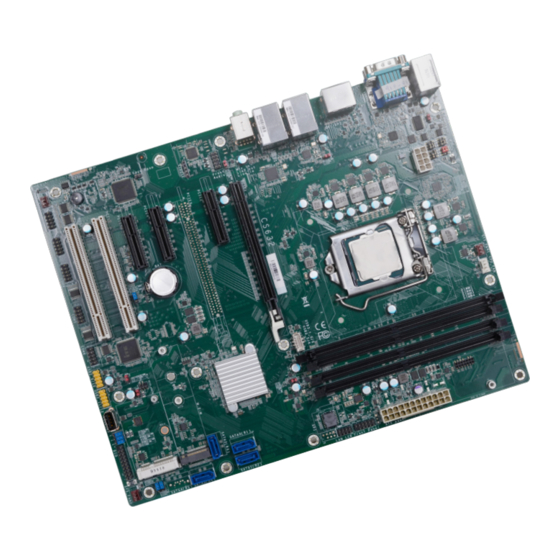
Chapter 2 HARDWARE INSTALLATION Chapter 2 - Hardware Installation X Board Layout Note: These optional components are only available upon request. DDR4_1 DDR4_3 USB 2.0 System Fan 1 (USB 7/8) PS/2 KB/MS JP27 +12V Power Important: Electrostatic discharge (ESD) can damage your board, processor, COM 1 disk drives, add-in boards, and other components. -
Page 10: System Memory
DIMMs of the same memory configuration are on different channels. Step 1 Features • CS632-C246: Four 288-pin ECC/Non-ECC DIMM up to 64GB • CS632-Q370: Four 288-pin Non-ECC DIMM up to 64GB • Dual Channel DDR4 2400/2666 MHz Step 2 User's Manual | CS632... -
Page 11: Removing The Dimm Module
Chapter 2 HARDWARE INSTALLATION System Memory Installing the DIMM Module System Memory Removing the DIMM Module Please follow the steps below to install the memory card into the socket. Please follow the steps below to remove the memory card from the socket. Step 1: Press the eject tabs at both ends of the socket outward and downward to release them from DDR4 DIMM... -
Page 12: Cpu
Chapter 2 HARDWARE INSTALLATION X CPU Installing the CPU 1. Make sure the PC and all other peripheral devices connected to it have been powered down. The system board is equipped with a surface mount LGA 1151 socket. This socket is exclu- sively designed for installing a LGA 1151 packaged Intel CPU. - Page 13 Chapter 2 HARDWARE INSTALLATION Installing the CPU Installing the CPU Load lever 5. Lift the load lever and the load 7-2. Two keys on the sock- et and notches on the Alignment key plate all the way up as shown in the photo.
-
Page 14: Installing The Fan And Heat Sink
Chapter 2 HARDWARE INSTALLATION Installing the Fan and Heat Sink 4. Screw tight two of the spring screws at opposite corners into the mounting holes. And The CPU must be kept cool by using a CPU fan with heat sink. Without sufficient air circula- then proceed with the other two spring screws. -
Page 15: Jumper Settings
Chapter 2 HARDWARE INSTALLATION COM 1 Serial Mode X Jumper Settings Clear CMOS „ COM 1 JP1, JP2, and JP3 are used to configure the COM 1 port to RS232, RS422 (Full Duplex) or RS485. The three jumpers must all be configured to the same serial mode. If any anomaly of the followings is encountered —... -
Page 16: Com1 Rs232 Power Select
Chapter 2 HARDWARE INSTALLATION Jumper Settings Jumper Settings COM1 RS232 Power Select Mini PCIe Power Select JP22 The COM 1 serial port supports RS232 with or without power configured via jumper settings of The power of Mini PCIe can be switched between 3V3DU and 3V3 via JP22. JP4. -
Page 17: Mini Pcie Signal Select
Chapter 2 HARDWARE INSTALLATION Jumper Settings Jumper Settings Mini PCIe Signal Select USB Power Select JP27 JP15 JP23 JP26 JP21 JP25 JP24 The signal of Mini PCIe can be switched between mSATA (default) or PCIe via JP21. The power of the USB connectors’ voltage buses can be configured to either 5VDU or 5V. The jumpers are located as illustrated above and correspond to each USB port number as listed. -
Page 18: Digital I/O (Dio) Power Select
Chapter 2 HARDWARE INSTALLATION Jumper Settings Jumper Settings Digital I/O (DIO) Power Select Digital I/O (DIO) Power Supply JP19 JP17 JP18 JP17 is used to select the power of Digital I/O: +5VDU (default) or +5V. The Digital I/O can be configured to use the power bus of the Digital I/O connector for power supply or not. -
Page 19: Power-On Select
Chapter 2 HARDWARE INSTALLATION Jumper Settings Power-on Select JP11 Power of the system can be turned on via the Power Button or via the AC-In signal. Switch the setting by putting the jumper caps on neighboring pins of JP11 as listed and illustrated below: „... -
Page 20: Rear I/O Ports
Chapter 2 HARDWARE INSTALLATION X Rear I/O Ports Rear I/O Ports PS/2 Keyboard/Mouse „ PS/2 KB/MS „ COM „ LAN 1 „ LAN 2 „ Audio „ 2 x DP++ „ PS/2 KB/MS „ 2 x USB 2.0 „ VGA „... -
Page 21: Usb Ports
Chapter 2 HARDWARE INSTALLATION Rear I/O Ports Rear I/O Ports USB Ports Graphics Display „ USB 8 (USB 2.0) „ USB 7 (USB 2.0) „ VGA „ DP++ 2 „ DP++ 1 „ USB 2 (USB 3.1 Gen 1) „ USB 4 (USB 3.1 Gen 1) The VGA port is used for connecting a VGA monitor. -
Page 22: Rj45 Lan
Chapter 2 HARDWARE INSTALLATION Rear I/O Ports Rear I/O Ports RJ45 LAN Audio „ LAN 1 „ LAN 2 „ Line-out „ Mic-in The two LAN ports allow the system board to connect to a local area network. The system board is equipped with three rear audio jacks: BIOS Setting •... -
Page 23: Com 1 (Serial) Port
Chapter 2 HARDWARE INSTALLATION Rear I/O Ports COM 1 (Serial) Port „ COM 1 „ COM 1 Pin Assignment Standard RS232 RS422 RS485 RS232 with Power DCD- +12V RXD+ Data+ RXD- Data- TXD+ N.C. DTR- DTR- TXD- N.C. DSR- DSR- N.C. -
Page 24: Internal I/O Connectors
Chapter 2 HARDWARE INSTALLATION X Internal I/O Connectors Internal I/O Connectors USB Ports COM (Serial) Ports „ USB 5/6 (USB 3.1 Gen 2) „ COM Port Pin Assignment RS232 DCD- „ USB 9/10 (left), 11/12 (right) (USB 2.0) Assignment Pin Assignment DTR- USB3_TX5+... -
Page 25: Front Audio
Chapter 2 HARDWARE INSTALLATION Internal I/O Connectors Internal I/O Connectors Front Audio SATA (Serial ATA) SATA1 SATA0 (R1) (R2) SATA2 (R3) „ Front Audio SATA3 (R4) SATA4 (R5) Note The Serial ATA (SATA) connectors are used to connect the Serial ATA device. SATA 3.0 is sup- ported by the five SATA ports and provides data rate up to 6Gb/s. -
Page 26: Digital I/O
Chapter 2 HARDWARE INSTALLATION Internal I/O Connectors Internal I/O Connectors Digital I/O Cooling Fan Connectors System Fan 1 (left), CPU Fan (right) „ System Fan 1/2/3 „ Digital I/O „ CPU Fan (PWM) System Fan 3 System Fan 2 The 8-bit Digital I/O (DIO) connector allows for input/output signals of digital logical states de- fined by voltage levels. -
Page 27: Power Connector
Chapter 2 HARDWARE INSTALLATION Internal I/O Connectors Internal I/O Connectors Power Connector Chassis Intrusion „ ATX 24-pin Power Connector 12 24 +3.3V +12V +12V +12V +5VSB „ ATX 8-pin Power PWR_OK Connector „ Chassis Intrusion PS_ON# +3.3V -12V +3.3V +3.3V 1 13 Use a power supply that complies with the ATX12V Power Supply Design Guide Version 1.1. -
Page 28: Front Panel
Chapter 2 HARDWARE INSTALLATION Internal I/O Connectors Internal I/O Connectors Front Panel S/PDIF PWR-LED HD-LED ATX-SW RESET „ S/PDIF Connector 11 12 „ Front Panel Connector „ Front Panel Pin Assignment Assignment Assignment N.C. LED Power The Sony/Philips Digital Interface (S/PDIF) connector is for audio output to external audio equipment. -
Page 29: Battery
Chapter 2 HARDWARE INSTALLATION Internal I/O Connectors Internal I/O Connectors Battery SMBus „ SMBus „ Battery Holder The lithium ion battery addendum supplies power to the real-time clock and CMOS memory The SMBus (System Management Bus) connector is used to connect the SMBus device. It is a as an auxiliary source of power when the main power is shut off. -
Page 30: Lpc
External COM port Module The LPC connector is used for debugging. The external COM port modules — EXT-RS232 and EXT-RS485 — are designed by DFI’s propri- etary technology, and support four additional COM ports per module. The EXT-RS232/RS485 card is connected to the motherboard via the LPC connector and secured by a standoff as il- lustrated below. -
Page 31: Lan Led
Chapter 2 HARDWARE INSTALLATION Internal I/O Connectors Internal I/O Connectors LAN LED Expansion Slots „ LAN LED Connector M.2 M Key Mini PCIe The LAN LED connector is used to detect the connection state of RJ45 LAN ports when the M.2 Sockets connection is made to an active network via a cable. -
Page 32: Installing The M.2 Module
Chapter 2 HARDWARE INSTALLATION Internal I/O Connectors Expansion Slots Internal I/O Connectors Expansion Slots Installing the M.2 Module Before installing the M.2 module into the M.2 socket, please make sure that the following safety cautions are well-attended. 1. Make sure the PC and all other peripheral devices connected to it has been powered down. -
Page 33: Installing The Mini Pcie Module
Chapter 2 HARDWARE INSTALLATION Internal I/O Connectors Expansion Slots Internal I/O Connectors Expansion Slots Installing the Mini PCIe Module Please follow the steps below to install the card into the socket. Before installing the Mini PCIe module into the Mini PCIe socket, please make sure that the fol- lowing safety cautions are well-attended. - Page 34 Chapter 2 HARDWARE INSTALLATION Internal I/O Connectors Expansion Slots Please follow the steps below to install the card into the socket. Step 1: Insert the card into the socket at an angle while making sure the notch and key are perfectly aligned. Step 2: Press the end of the card far from the socket down until against the...
-
Page 35: Chapter 3 - Bios Settings
Chapter 3 BIOS SETTINGS Chapter 3 - BIOS Settings Legends X Overview The BIOS is a program that takes care of the basic level of communication between the CPU Keys Function and peripherals. It contains codes for various advanced features found in this system board. The BIOS allows you to configure the system and save the configuration in a battery-backed Right / Left arrow Move the highlight left or right to select a menu... -
Page 36: Main
Chapter 3 BIOS SETTINGS X Main X Advanced The Main menu is the first screen that you will see when you enter the BIOS Setup Utility. The Advanced menu allows you to configure your system for basic operation. Some entries are defaults required by the system board, while others, if enabled, will improve the performance of your system or let you set some features according to your preference. -
Page 37: Rc Acpi Configuration
Chapter 3 BIOS SETTINGS Advanced Advanced RC ACPI Configuration CPU Configuration Aptio Setup Utility - Copyright (C) 2019 American Megatrends, Inc. Aptio Setup Utility - Copyright (C) 2019 American Megatrends, Inc. Advanced Advanced CPU Configuration When enabled, a VMM can RC ACPI Configuration Enable or disable System utilize the additional hard-... -
Page 38: Power & Performance
Chapter 3 BIOS SETTINGS Advanced Advanced Power & Performance PCH-FW Configuration Aptio Setup Utility - Copyright (C) 2019 American Megatrends, Inc. Aptio Setup Utility - Copyright (C) 2019 American Megatrends, Inc. Advanced Advanced ME State [Enabled] When Disabled ME will be Power &... - Page 39 Chapter 3 BIOS SETTINGS Advanced PCH-FW Configuration Advanced PCH-FW Configuration ► AMT Configuration ► AMT Configuration ► Secure Erase Configuration Aptio Setup Utility - Copyright (C) 2019 American Megatrends, Inc. Aptio Setup Utility - Copyright (C) 2019 American Megatrends, Inc. Advanced Advanced USB Provisioning of AMT...
- Page 40 Chapter 3 BIOS SETTINGS Advanced PCH-FW Configuration Advanced PCH-FW Configuration ► AMT Configuration ► OEM Flags Settings ► Firmware Update Configuration Aptio Setup Utility - Copyright (C) 2019 American Megatrends, Inc. Aptio Setup Utility - Copyright (C) 2019 American Megatrends, Inc. Advanced Advanced Me FW Image Re-Flash...
-
Page 41: Trusted Computing
Chapter 3 BIOS SETTINGS Advanced Advanced Trusted Computing NCT6116D Super IO Configuration Aptio Setup Utility - Copyright (C) 2019 American Megatrends, Inc. Aptio Setup Utility - Copyright (C) 2019 American Megatrends, Inc. Advanced Advanced TPM20 Device Found Enables or Disables BIOS NCT6116D Super IO Configuration WatchDog Timer Unit Se- Firmware Version... -
Page 42: Nct6116D Hw Monitor
Chapter 3 BIOS SETTINGS Advanced NCT6116D Super IO Configuration Advanced ► Serial Port 1/2/3/4/5/6 Configuration NCT6116D HW Monitor Aptio Setup Utility - Copyright (C) 2019 American Megatrends, Inc. Aptio Setup Utility - Copyright (C) 2019 American Megatrends, Inc. Advanced Advanced Serial Port 1 Configuration Enable or Disable Serial Smart Fan function setting... -
Page 43: Serial Port Console Redirection
Chapter 3 BIOS SETTINGS Advanced NCT6116D HW Monitor Advanced ► Smart Fan Function Serial Port Console Redirection Aptio Setup Utility - Copyright (C) 2019 American Megatrends, Inc. Aptio Setup Utility - Copyright (C) 2019 American Megatrends, Inc. Advanced Advanced Enable CPU SmartFan Console Redirection En - Smart Fan Function COM1... -
Page 44: Usb Configuration
Chapter 3 BIOS SETTINGS Advanced Serial Port Console Redirection Advanced ► Console Redirection Settings USB Configuration Aptio Setup Utility - Copyright (C) 2019 American Megatrends, Inc. Aptio Setup Utility - Copyright (C) 2019 American Megatrends, Inc. Advanced Advanced Enable CPU SmartFan Enables Legacy USB sup- COM1 USB Configuration... -
Page 45: Csm Configuration
Chapter 3 BIOS SETTINGS Advanced Advanced CSM Configuration Network Stack Configuration Aptio Setup Utility - Copyright (C) 2019 American Megatrends, Inc. Aptio Setup Utility - Copyright (C) 2019 American Megatrends, Inc. Advanced Advanced Enable/Disable CSM Sup- Enable/Disable UEFI Net- Compatibility Support Module Configuration Network Stack [Enabled] port. -
Page 46: Chipset
Chapter 3 BIOS SETTINGS X Chipset Chipset Graphics Configuration Aptio Setup Utility - Copyright (C) 2019 American Megatrends, Inc. Aptio Setup Utility - Copyright (C) 2019 American Megatrends, Inc. Main Advanced Chipset Security Boot Save & Exit Chipset ► Graphics Configuration Graphics Configuration Initial priority : Graphics Configuration... -
Page 47: Peg Port Configuration
Chapter 3 BIOS SETTINGS Chipset PEG Port Configuration ► PEG Port Feature Configuration Aptio Setup Utility - Copyright (C) 2019 American Megatrends, Inc. Aptio Setup Utility - Copyright (C) 2019 American Megatrends, Inc. Chipset Chipset Enable or Disable the Root Detect Non-Compliance PCI PEG Port Configuration PEG Port Feature Configuration... -
Page 48: Pch-Io Configuration
Chapter 3 BIOS SETTINGS Chipset Chipset PCH-IO Configuration PCH-IO Configuration PCI Express Configuration Aptio Setup Utility - Copyright (C) 2019 American Megatrends, Inc. Aptio Setup Utility - Copyright (C) 2019 American Megatrends, Inc. Chipset Chipset PCI Express Configuration PCI Express Root Port Set- PCH-IO Configuration PCI Express Configuration settings... -
Page 49: Sata And Rst Configuration
Chapter 3 BIOS SETTINGS Chipset PCH-IO Configuration Chipset PCH-IO Configuration SATA And RST Configuration HD Audio Configuration Aptio Setup Utility - Copyright (C) 2019 American Megatrends, Inc. Aptio Setup Utility - Copyright (C) 2019 American Megatrends, Inc. Chipset Chipset SATA And RST Configuration E n a b l e o r d i s a b l e S ATA Control Detection of the HD Audio Subsystem Configuration Settings... -
Page 50: Security
Chapter 3 BIOS SETTINGS X Security Security Secure Boot Aptio Setup Utility - Copyright (C) 2019 American Megatrends, Inc. Aptio Setup Utility - Copyright (C) 2019 American Megatrends, Inc. Main Advanced Chipset Security Boot Save & Exit Security Password Description S e t A d m i n i s t r a t o r P a s s - System Mode Setup... -
Page 51: Boot
Chapter 3 BIOS SETTINGS X Boot X Save & Exit Aptio Setup Utility - Copyright (C) 2019 American Megatrends, Inc. Aptio Setup Utility - Copyright (C) 2019 American Megatrends, Inc. Main Advanced Chipset Security Boot Save & Exit Main Advanced Chipset Security Boot... -
Page 52: Updating The Bios
BIOS with the flash utility. For updating AMI BIOS in UEFI mode, you may refer to the how-to video at https://www.dfi.com/Knowledge/Video/5. X Notice: BIOS SPI ROM 1. -
Page 53: Chapter 4 - Intel Amt Settings
Chapter 4 INTEL AMT SETTINGS Chapter 4 - Intel AMT Settings X Enable Intel AMT in the AMI BIOS ® 1. Power-on the system then press <Del> to enter the main menu of the AMI BIOS. X Overview 2. In the Advanced menu, select PCH-FW Configuration. Intel Active Management Technology (Intel AMT) combines hardware and software solution to ®... -
Page 54: Entering Management Engine Bios Extension (Mebx)
Chapter 4 INTEL AMT SETTINGS Enable Intel ® AMT in the AMI BIOS X Entering Management Engine BIOS Extension (MEBX) 4. Press F4, or go to the Save & Exit menu, select Save Changes and Reset and then press <Enter>. A dialog box will appear. Select Yes and press Enter to reset the system after saving all changes made. -
Page 55: Mebx
Chapter 4 INTEL AMT SETTINGS X MEBX Intel(R) ME General Settings Main Menu Select MEBx Login under Main Menu and press Enter. A prompt that requires password input Select Intel(R) ME General Settings under Main Menu and then press Enter. will show up. - Page 56 Chapter 4 INTEL AMT SETTINGS MEBX Intel(R) ME General Settings MEBX Intel(R) ME General Settings Change ME Password Local FW Update If you want to change ME password, select Change ME Password and then press Enter. A Select Local FW Update then press Enter. Select Enabled or Disabled or Password Protected prompt that requires password input will show up.
-
Page 57: Intel(R) Amt Configuration
Chapter 4 INTEL AMT SETTINGS MEBX Intel(R) AMT Configuration > SOL/Storage Redirection/KVM Select Intel(R) AMT Configuration under Main Menu and then press Enter. Intel(R) Management Engine BIOS Extension v12.0.0.0010/Intel(R) ME v12.0.40.1433 Intel(R) Management Engine BIOS Extension v12.0.0.0010/Intel(R) ME v12.0.40.1433 Copyright(C) 2003-17 Intel Corporation. All Rights Reserved Copyright(C) 2003-17 Intel Corporation. - Page 58 Chapter 4 INTEL AMT SETTINGS MEBX Intel(R) AMT Configuration MEBX Intel(R) AMT Configuration > SOL/Storage Redirection/KVM > User Consent Intel(R) Management Engine BIOS Extension v12.0.0.0010/Intel(R) ME v12.0.40.1433 Intel(R) Management Engine BIOS Extension v12.0.0.0010/Intel(R) ME v12.0.40.1433 Copyright(C) 2003-17 Intel Corporation. All Rights Reserved Copyright(C) 2003-17 Intel Corporation.
- Page 59 Chapter 4 INTEL AMT SETTINGS MEBX Intel(R) AMT Configuration MEBX Intel(R) AMT Configuration > User Consent Password Policy Intel(R) Management Engine BIOS Extension v12.0.0.0010/Intel(R) ME v12.0.40.1433 Intel(R) Management Engine BIOS Extension v12.0.0.0010/Intel(R) ME v12.0.40.1433 Copyright(C) 2003-17 Intel Corporation. All Rights Reserved Copyright(C) 2003-17 Intel Corporation.
- Page 60 Chapter 4 INTEL AMT SETTINGS MEBX Intel(R) AMT Configuration > Network Setup Move the cursor to select a field and press Enter to display options. Under the Intel(R) AMT Configuration menu, select Network Setup and then press Enter. Intel(R) Management Engine BIOS Extension v12.0.0.0010/Intel(R) ME v12.0.40.1433 Intel(R) Management Engine BIOS Extension v12.0.0.0010/Intel(R) ME v12.0.40.1433 Copyright(C) 2003-17 Intel Corporation.
- Page 61 Chapter 4 INTEL AMT SETTINGS MEBX Intel(R) AMT Configuration Network Setup Intel(R) ME Network Name Settings MEBX Intel(R) AMT Configuration Network Setup Dynamic DNS Update > TCP/IP Settings Select Enabled or Disabled then press Enter. When Dynamic DNS Update is Enabled, the follow- Under the Intel(R) ME Network Setup menu, select TCP/IP Settings and then press Enter.
- Page 62 Chapter 4 INTEL AMT SETTINGS MEBX Intel(R) AMT Configuration Network Setup TCP/IP Settings DHCP Mode IPv4 Address Select Enabled or Disabled then press Enter. Please make sure there is a DHCP server in the Assign a valid and available IP address to the system. Insert a value from 0.0.0.0 to network when this field is enabled.
- Page 63 Chapter 4 INTEL AMT SETTINGS MEBX Intel(R) AMT Configuration MEBX Intel(R) AMT Configuration Activate Network Access Unconfigure Network Access Under the Intel(R) AMT Configuration menu, select Activate Network Access and press Enter, Under the Intel(R) AMT Configuration menu, select Undconfigure Network Access and press and then press Y to activate the ME network connection with the settings configured previ- Enter, and then press Enter to fully deactivate the ME network connection and reset configura- ously, or press N to abort.
- Page 64 Chapter 4 INTEL AMT SETTINGS MEBX Intel(R) AMT Configuration > Remote Setup And Configuration Under the Intel(R) AMT Configuration menu, select Remote Setup And Configuration then Current Provisioning Mode press Enter. The current mode — Public Key Infrastructure (PKI) — is displayed. Intel(R) Management Engine BIOS Extension v12.0.0.0010/Intel(R) ME v12.0.40.1433 Copyright(C) 2003-17 Intel Corporation.
- Page 65 Chapter 4 INTEL AMT SETTINGS MEBX Intel(R) AMT Configuration Remote Setup And Configuration MEBX Intel(R) AMT Configuration Remote Setup And Configuration > RCFG > TLS PKI Press Enter, select Start Configuration, and then press Enter to activate Remote Configuration The system adopts PKI for encryption and authentication, and the TLS protocol for communica- (RCFG).
- Page 66 Chapter 4 INTEL AMT SETTINGS MEBX Intel(R) AMT Configuration Remote Setup And Configuration TLS PKI MEBX Intel(R) AMT Configuration > Power Control Under the Intel(R) AMT Configuration menu, select Power Control then press Enter. > Manage Hashes Intel(R) Management Engine BIOS Extension v12.0.0.0010/Intel(R) ME v12.0.40.1433 Select a hash name and then press the following keys to execute a function.
- Page 67 Chapter 4 INTEL AMT SETTINGS MEBX MEBx Exit Under the Main Menu, select MEBx Exit and then press Enter. Press Y to confirm or N to abort. Intel(R) Management Engine BIOS Extension v12.0.0.0010/Intel(R) ME v12.0.40.1433 Copyright(C) 2003-17 Intel Corporation. All Rights Reserved MAIN MENU >...
-
Page 68: Chapter 5 - Raid
Chapter 5 RAID Chapter 5 - RAID X Setup Procedure The system board allows configuring RAID on Serial ATA drives. It supports RAID 0, RAID 1, RAID 5 and RAID 10. To enable the RAID function, the following settings are required. X RAID Levels 1. - Page 69 Chapter 5 RAID Step 3: Create a RAID Volume Step 4: Install the Intel Rapid Storage Technology Utility 1. Go to the “Advanced” menu of the AMI BIOS and select “Intel(R) Rapid Storage Technol- The Intel Rapid Storage Technology Utility can be installed from within Windows. It allows RAID ogy”.
-
Page 70: Chapter 6 - Supported Software
Intel chipset can be recognized and configured properly in the system. tives, from an optional DVD included in the shipment, or from the website download page at https://www.dfi.com/DownloadCenter. 1. Setup is ready to install the util- X Auto-run Menu ity. -
Page 71: Intel Hd Graphics Drivers
Chapter 6 SUPPORTED SOFTWARE X Intel HD Graphics Drivers 3. Go through the readme docu- ment for more installation tips then click “Install”. 1. Setup is now ready to install the graphics driver. Click “Next”. 4. The step displays the installing status in the progress. -
Page 72: Realtek Audio Drivers
Chapter 6 SUPPORTED SOFTWARE X Realtek Audio Drivers 3. Go through the readme docu- ment for system requirements and installation tips then click “Next”. 1. Setup is ready to install the driver. Click “Next”. 4. Setup is now installing the driver. -
Page 73: Intel Lan Driver
Chapter 6 SUPPORTED SOFTWARE X Intel LAN Driver 4. Click “Install” to begin the in- stallation. 1. Setup is ready to install the driver. Click “Next”. 5. The step displays the installing status in the progress. 2. Click “I accept the terms in the license agreement”... -
Page 74: Intel Me Drivers
Chapter 6 SUPPORTED SOFTWARE X Intel ME Drivers 3. Click “Next” to install to the 1. Setup is ready to install the default folder, or click “Change” driver. Click “Next”. to choose another destination folder. 4. Please wait while the product 2. -
Page 75: Intel Serial Io Drivers
Chapter 6 SUPPORTED SOFTWARE X Intel Serial IO Drivers 3. Go through the readme docu- 1. Setup is ready to install the ment for system requirements driver. Click “Next”. and installation tips then click “Next”. 2. Read the license agreement carefully. -
Page 76: Intel Rapid Storage Technology
Chapter 6 SUPPORTED SOFTWARE X Intel Rapid Storage Technology The Intel Rapid Storage Technology is a utility that allows you to monitor the current status 5. Setup is now installing the driver. of the SATA drives. It enables enhanced performance and power management for the storage subsystem. - Page 77 Chapter 6 SUPPORTED SOFTWARE 3. Go through the readme docu- 6. Click “Yes, I want to restart this ment to view system require- computer now” to complete the ments and installation informa- installation and then click “Fin- tion then click “Next”. ish”.
-
Page 78: Adobe Acrobat Reader 9.3
Chapter 6 SUPPORTED SOFTWARE X Adobe Acrobat Reader 9.3 1. Click “Next” to install or click 3. Setup is now installing the driver. “Change Destination Folder” to select another folder. 2. Click “Install” to begin installa- 4. Click “Finish” to exit installa- tion.
Need help?
Do you have a question about the CS632-Q370 and is the answer not in the manual?
Questions and answers