Table of Contents
Advertisement
Quick Links
Advertisement
Table of Contents

Related Manuals for DFI CS620-H310


Summary of Contents for DFI CS620-H310
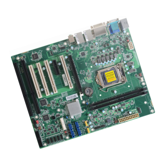
- Page 1 CS620-H310 ATX Industrial Motherboard User’s Manual Preliminary A-611-M-2039...
- Page 2 1. The changes or modifications not expressly approved by the party responsible for com- pliance could void the user’s authority to operate the equipment. 2. Shielded interface cables must be used in order to comply with the emission limits. User's Manual | CS620-H310...
-
Page 3: Table Of Contents
S/PDIF..........................26 Battery ..........................27 SMBus ..........................27 LPC ..........................28 External COM port Module ...................28 LAN LED .........................29 Expansion Slots ......................29 Installing the Mini PCIe Module ...................30 Chapter 3 - BIOS Settings ......................31 Overview ..........................31 Main ............................32 Advanced ..........................32 User's Manual | CS620-H310... - Page 4 • To reduce the risk of electric shock, unplug the power cord before removing the sys- tem chassis cover for installation or servicing. After installation or servicing, cover the system chassis before plugging the power cord. User's Manual | CS620-H310...
- Page 5 DP to HDMI dongle 612-D2H13M-000G • LPC EXT-RS232 module 770-EXTRS1-000G 4 x RS232 ports • LPC EXT-RS485 module 770-EXTRS1-100G 4 x RS485 ports The board and accessories in the package may not come similar to the information listed User's Manual | CS620-H310...
-
Page 6: Chapter 1 - Introduction
1 x DP++ resolution up to 4096x2160 @ 60Hz MECHANICAL Dimensions ATX Form Factor: 305mm (12") x 244mm (9.6") Multiple VGA + DVI-D / VGA + DP++ / DP++ + DVI-D Height PCB: 1.6mm Displays CERTIFICATIONS CE, FCC Class B User's Manual | CS620-H310... -
Page 7: Features
IRQ or DMA interrupt. Wake-On-USB This function allows you to use a USB keyboard or USB mouse to wake up a system from the S3 (STR - Suspend To RAM) state. User's Manual | CS620-H310... -
Page 8: Chapter 2 - Hardware Installation
When the Standby Power LED lit red, it indicates that there is power on the system board. Power-off the PC then unplug the Digital I/O power cord prior to installing any devices. Failure to do so will cause severe damage to the motherboard and components. User's Manual | CS620-H310... -
Page 9: System Memory
DIMMs. Not all slots need to be populated. Dual Channel DIMMs of the same memory configuration are on different channels. Step 1 Features • Two 288-pin UDIMM up to 64GB (non-ECC support) • Dual Channel DDR4 2400/2666MHz User's Manual | CS620-H310 Step 2... -
Page 10: Removing The Dimm Module
Hold the card by its edges and remove it from the slot. Step 1 Step 1 Step 1 Step 1 Step 2 Step 2 Step 2 Step 2 Step 3 Step 3 Step 3 Step 3 User's Manual | CS620-H310... -
Page 11: Cpu
Lift the load lever up when Note: it’s released. The system board used in the following illustrations may not resemble the actual board. These illustrations and photos are for reference only. Load lever Retention tab User's Manual | CS620-H310... - Page 12 Load lever 9. Press down the load lever Retention knob and hook it under the reten- tion tab. Important: The CPU will fit in only one orientation and can easily be seated without exerting any force. User's Manual | CS620-H310...
-
Page 13: Installing The Fan And Heat Sink
SATA 0 SATA 1 H310 PCI 2 SATA 2 SATA 3 JP21 PCI 3 TSJP7 J12 SMBus TSJP5 PCI 4 mSATA / Mini PCIe SOJ1 ISA 1 Buzzer JP18/19/17 ISA 2 3 3 3 System Fan 3 User's Manual | CS620-H310... -
Page 14: Jumper Settings
1 and pin 2. 3. Plug the power cord and power-on the system. TSJP3 & TSJP4 „ 1-3, 2-4 On „ 3-5, 4-6 On „ 3-5, 4-6 On „ 1-2 On: Normal (default) „ 2-3 On: Clear CMOS User's Manual | CS620-H310... -
Page 15: Com 2 Serial Mode
3-5 On: Pin 9 = +5V TSJP6 TSJP5 (COM2) „ 1-3, 4-6 On „ 3-5, 4-6 On „ 3-5, 2-4 On TSJP1 TSJP7 & (COM1) TSJP8 „ 1-3, 2-4 On „ 3-5, 4-6 On „ 3-5, 4-6 On User's Manual | CS620-H310... -
Page 16: Sata Port0 / Msata Switch
JP18 is used to select for DIO0~DIO3. JP19 is used to select for DIO4~DIO7. via JP21. „ 1-2 On: DIO power used (default) „ 2-3 On: GND „ 1-2 On: 7-pin SATA connector (SATA0) „ 2-3 On: mSATA via Mini PCIe (default) User's Manual | CS620-H310... -
Page 17: Digital I/O (Dio) Power Select
SOJ1 ISA 1 Buzzer JP18/19/17 ISA 2 3 3 3 System Fan 3 JP17 is used to select the power of Digital I/O: +5VDU (default) or +5V. „ 1-2 On: +5VDU (default) „ 2-3 On: +5V User's Manual | CS620-H310... -
Page 18: Rear I/O Ports
1 VGA port (DB15) • 1 DP++ port • 1 DVI-I port • 2 LAN ports (RJ45 ) • 4 USB 3.1 Gen1 ports • 1 Line-in jack (optional) • 1 Line-out jack • 1 Mic-in jack User's Manual | CS620-H310... -
Page 19: Usb Ports
The Wake-On-USB Keyboard/Mouse function allows you to use a USB keyboard or USB mouse to wake up a system from the S3 (STR - Suspend To RAM) state. User's Manual | CS620-H310... -
Page 20: Rj45 Lan
This jack is used to connect a headphone or external speakers. • Mic-in Jack (Pink) This jack is used to connect an external microphone. For the internal Front Audio connector, please refer to the next section. User's Manual | CS620-H310... -
Page 21: Com 1 (Serial) Port
Serial mode and RS232 with/without power of COM 2 are configured via jumper settings as previously instructed in this chapter. previously instructed in this chapter. Note: Please refer to the Internal I/O section later in this chapter for more information on the internal COM ports. User's Manual | CS620-H310... -
Page 22: Usb Ports
USB port cables to a connector. Wake-On-USB Keyboard/Mouse The Wake-On-USB Keyboard/Mouse function allows you to use a USB keyboard or USB mouse to wake up a system from the S state(s). User's Manual | CS620-H310... -
Page 23: Front Audio
N.C. Line2-R Mic2-JD Front I/O Sense Line2-L Line2-JD Note: The SATA bus of SATA3 (R5) is shared with Mini PCIe (mSATA), and will be inac- tive when the SATA bus is directed to Mini PCIe (mSATA). User's Manual | CS620-H310... -
Page 24: Digital I/O
BIOS. Refer to chapter 3 for more information. +12V DIO_7 +12V DIO_6 „ 3-pin Fan Pin Assignment „ 4-pin Fan Pin Assignment DIO_5 Pin Assignment Pin Assignment DIO_4 Ground Ground DIO_3 Power Power DIO_2 +5VDU DIO_1 +5VDU Sense Sense DIO_0 Speed Control User's Manual | CS620-H310... -
Page 25: Power Connector
Insufficient power supplied to the system may result in instability or malfunction of the add-in boards and peripherals. Calculating the system’s approximate power usage is important to ensure that the power supply meets the system’s consump- tion requirements. User's Manual | CS620-H310... -
Page 26: Front Panel
Power On Suspend) state, it will blink at 1-second intervals. When the system is in the S3 (STR - Suspend To RAM) state, it will blink at 4-second intervals. ATX-SW - ATX Power Switch This switch is used to power on or off the system. User's Manual | CS620-H310... -
Page 27: Battery
• There exists explosion hazard if the battery is incorrectly installed. 3V3DU • Replace only with the same or equivalent type recommended by the manufacturer. SMBus_Clock SMBus_DATA • Dispose of used batteries according to local ordinances. SMBus_Alert User's Manual | CS620-H310... -
Page 28: Lpc
External COM port Module The LPC connector is used for debugging. The external COM port modules — EXT-RS232 and EXT-RS485 — are designed by DFI’s propri- etary technology, and support four additional COM ports per module. The EXT-RS232/RS485 card is connected to the motherboard via the LPC connector and secured by a standoff as illustrated below. -
Page 29: Lan Led
SATA, and USB signals. Jumper Setting Select the signal of Mini PCIe via jumper settings as previously instructed in this chapter. „ LAN LED Pin Assignment Pin Assignment Pin Assignment GBE(LAN1)_1000 GBE(LAN1)_100 GBE(LAN1)_LED_LINK_ACT 3V3DU LINK(LAN2)_1000 LINK(LAN2)_100 LINK(LAN2)_ACTIVITY 3V3DU User's Manual | CS620-H310... -
Page 30: Installing The Mini Pcie Module
PCI expansion card or a customized riser card designed for only 2 PCI slots expansion (for low profile PCI card only) into the PCI slot. ISA Slot The ISA slot is used to connect ISA-compatible expansion cards. User's Manual | CS620-H310... -
Page 31: Chapter 3 - Bios Settings
When “X” appears on the left of a particular field, it indicates that a submenu which contains additional options are available for that field. To display the submenu, move the highlight to that field and press <Enter>. User's Manual | CS620-H310... -
Page 32: Main
The time format is <hour>, <minute>, <second>. The time is based on the 24-hour military-time clock. For example, 1 p.m. is 13:00:00. Hour displays hours from 00 to 23. Minute displays minutes from 00 to 59. Second displays seconds from 00 to 59. User's Manual | CS620-H310... -
Page 33: Rc Acpi Configuration
Last State The system returns to the last state right before power failure. Note: Some of the fields may not be available when the features are not supported by the equipped CPU. User's Manual | CS620-H310... -
Page 34: Power & Performance
Enable or disable turbo mode of the processor. This field will only be displayed when EIST is enabled. C states Enable or disable CPU Power Management. It allows CPU to enter "C states" when it’s idle and nothing is executing. Note: The sub-menus are detailed in following sections. User's Manual | CS620-H310... - Page 35 ESC: Exit Version 2.20.1275. Copyright (C) 2020 American Megatrends, Inc. Me FW Image Re-Flash This field is used to enable or disable the ME FW Image Re-Flash function, which allows the user to update the ME firmware. User's Manual | CS620-H310...
-
Page 36: Trusted Computing
Set SuperIO WatchDog Timer Timeout value. The range is from 0 (disabled) to 255. To clear the existing TPM encryption, select "TPM Clear" and restart the system. This field is not available when "Security Device Support" is disabled. Note: The sub-menus are detailed in following sections. User's Manual | CS620-H310... -
Page 37: Nct6116D Hw Monitor
Enable or disable the current serial COM port. Case Open RS485 Auto Flow Enable or disable the case open detection function. Enable or disable RS485 auto flow. This field is only available for COM ports that support RS485 mode. User's Manual | CS620-H310... -
Page 38: Serial Port Console Redirection
▼ SYS Smart Fan/CPU Smart Fan Control = [Disabled] Fix Fan Speed Count Set the fan speed, the value ranging from 1-100%, 100% being full speed. The fans will always operate at the specified speed regardless of gauged temperatures. User's Manual | CS620-H310... -
Page 39: Usb Configuration
Select parity bits: None, Even, Odd, Mark or Space. Stop Bits Select stop bits: 1 bit or 2 bits. Flow Control Select flow control type: None or Hardware RTS/CTS. Flow Control is for RS485 mode and is only supported by Serial Port 1 (COM1). User's Manual | CS620-H310... -
Page 40: Csm Configuration
This field controls the execution of UEFI and Legacy Storage OpROM. Video This field controls the execution of UEFI and Legacy Video OpROM. Other PCI devices This field determines OpROM execution policy for devices other than Network, Storage or Video. User's Manual | CS620-H310... -
Page 41: Network Stack Configuration
Set the wait time in seconds to press ESC key to abort the PXE boot. Use either +/- or numeric keys to set the value. Media detect count Set the number of times the presence of media will be checked. Use either +/- or numeric keys to set the value. User's Manual | CS620-H310... -
Page 42: Chipset
Please select a submenu and press Enter. The submenus are detailed in the following pages. Primary Display Select which of IGFX/PEG/PCI Graphics device to be the primary display. Internal Graphics Keep IGFX "Enabled" or "Disabled" based on the setup options, or select "Auto" for auto-detec- tion. User's Manual | CS620-H310... -
Page 43: Peg Port Configuration
Enable or disable the root port, or select "Auto" for auto-detection. Enable or disable this field to detect non-compliance PCIe devices in the PEG. Max Link Speed Configure PCIE1 port’s Max Speed: Auto, Gen1, Gen2 or Gen3. User's Manual | CS620-H310... -
Page 44: Pch-Io Configuration
Detect Non-Compliance Device Enable or disable this field to detect non-compliance PCIe devices in the PEG. This field may not appear when the port does not support Non-compliant device detection. Note: The sub-menus are detailed in following sections. User's Manual | CS620-H310... -
Page 45: Sata And Rst Configuration
This field shows up when SATA Mode Selection is set to Intel RST Premium With Intel Optane System Acceleration. Enable or disable to use RST Legacy OROM when CSM is enabled. Ports and Hot Plug Enable or disable the Serial ATA port and its hot plug function. User's Manual | CS620-H310... -
Page 46: Security
Secure Boot. Press Enter and a prompt will show up for you to confirm. Reset To Setup Mode Clear the database from the NVRAM, including all the keys and signatures installed in the Key Management menu. Press Enter and a prompt will show up for you to confirm. User's Manual | CS620-H310... -
Page 47: Boot
Refer to the Advanced > CSM Configuration submenu for more information. This field will appear only when a USB flash device is detected. Select this field to restore set- ting from the USB flash device. User's Manual | CS620-H310... -
Page 48: Updating The Bios
When the BIOS IC needs to be replaced, you have to populate it properly onto the system board after the EEPROM programmer has been burned and follow the technical person's instructions to confirm that the MAC address should be burned or not. User's Manual | CS620-H310 ver.011_EVT_10-520_11-42...
Need help?
Do you have a question about the CS620-H310 and is the answer not in the manual?
Questions and answers