Table of Contents
Advertisement
Quick Links
Advertisement
Table of Contents

Related Manuals for DFI CS630-Q370


Summary of Contents for DFI CS630-Q370
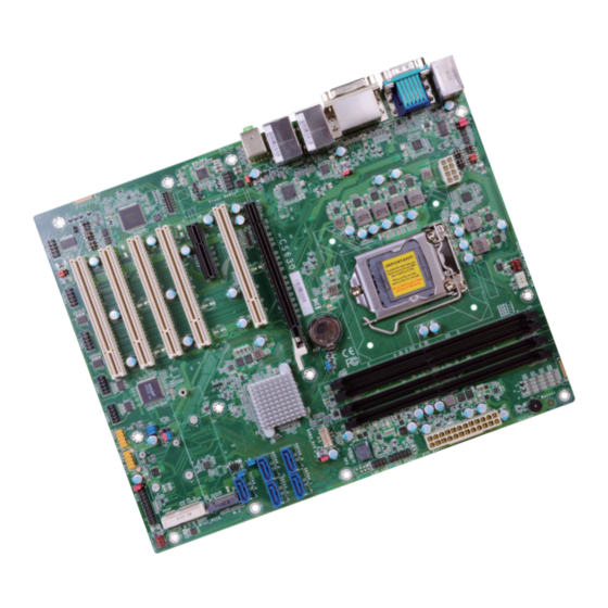
- Page 1 CS630-H310/Q370 ATX Industrial Motherboard User’s Manual A49500852...
-
Page 2: Copyright
Copyright FCC and DOC Statement on Class B This publication contains information that is protected by copyright. No part of it may be re- This equipment has been tested and found to comply with the limits for a Class B digital produced in any form or by any means or used to make any transformation/adaptation without device, pursuant to Part 15 of the FCC rules. -
Page 3: Table Of Contents
Clear CMOS Data ..................17 USB Power Select ..................17 Mini PCIe/mSATA Signal Select (for CS630-Q370 only)........18 Mini PCIe/mSATA Power Select (for CS630-Q370 only) ......... 18 Digital I/O Power Select ................19 Digital I/O Output State ................19 PS/2 Power Select ..................20 Rear Panel I/O Ports ................. -
Page 4: Warranty
Warranty Static Electricity Precautions 1. Warranty does not cover damages or failures that arised from misuse of the product, It is quite easy to inadvertently damage your PC, system board, components or devices even inability to use the product, unauthorized replacement or alteration of components and before installing them in your system unit. -
Page 5: About The Package
About the Package The package contains the following items. If any of these items are missing or damaged, please contact your dealer or sales representative for assistance. • One CS630-H310/Q370 motherboard • One COM port cable (with Bracket, Length: 300mm, 2 x COM ports) •... -
Page 6: Chapter 1 - Introduction
Chapter 1 - Introduction CS630-H310 Specifications REAR I/O Ethernet 2 x GbE (RJ-45) SYSTEM Processor 8th Generation Intel Core™ /Pentium ® /Celeron ® LGA 1151 Socket Processors, ® TDP support up to 95W: 4 x USB 3.1 Gen1 ® Intel Core™... - Page 7 CS630-Q370 Specifications SYSTEM REAR I/O Ethernet 2 x GbE (RJ-45) ® ® Processor 8th Generation Intel ® Core™ /Pentium /Celeron LGA 1151 Socket Processors, TDP support up to 95W: ® Intel Core™ i7-8700 (6 Cores, 12M Cache, up to 4.6 GHz); 65W 4 x USB 3.1 Gen1...
-
Page 8: Features
® ment and Plug-and-Play with operating systems that support OS Direct Power Management. support up to 1Gbps data transmission for CS630-Q370. ACPI when enabled in the Power Management Setup will allow you to use the Suspend to RAM • Audio function. -
Page 9: Chapter 2 - Hardware Installation
Digital I/O 0-3 Output State Output (JP18) Chassis State Intrusion • Two 288-pin DIMM up to 32GB (CS630-H310) (JP19) Four 288-pin DIMM up to 64GB (CS630-Q370) System Fan 2 COM 2 COM 3 COM 4 COM 5 COM 6 COM 2 •... -
Page 10: Installing The Dimm Module
Chapter 2 The system board supports the following memory interface. Installing the DIMM Module Single Channel (SC) Note: The system board used in the following illustrations may not resemble the actual Data will be accessed in chunks of 64 bits (8B) from the memory channels. board. -
Page 11: Cpu
Chapter 2 6. Grasping the module by its edges, position the module above the socket with the “notch” in the module aligned with the “key” on the socket. The keying mechanism ensures the module can be plugged into the socket in only one way. The system board is equipped with a surface mount LGA 1151 socket. -
Page 12: Installing The Cpu
Chapter 2 Load lever 5. Lift the load lever to lift Installing the CPU the load plate. 1. Make sure the PC and all other peripheral devices connected to it has been powered down. Lift the load lever up to the angle shown on the 2. - Page 13 Chapter 2 7. Insert the CPU into the 8. Close the load plate then Load lever socket. The gold triangular push the load lever down. mark on the CPU must align with the corner of While closing the load the CPU socket shown on plate, make sure the front Retention knob edge of the load plate...
-
Page 14: Installing The Fan And Heat Sink
Chapter 2 Installing the Fan and Heat Sink 4. Rotate each push-pin ac- cording to the direction of the arrow shown on top of The CPU must be kept cool by using a CPU fan with heat sink. Without sufficient air circula- the pin. -
Page 15: Jumper Settings
Chapter 2 Jumper Settings JP1 (for COM 1)/JP10 (for COM 2) 2 4 6 2 4 6 2 4 6 2 4 6 2 4 6 2 4 6 COM1/COM2 RS232/422/485 Select JP1 (for COM1) 1 3 5 1 3 5 1 3 5 1 3 5 1 3 5... -
Page 16: Com1/Com2 Rs232/Power Select
Chapter 2 COM1/COM2 RS232/Power Select JP4 (for COM 1) 2 4 6 2 4 6 JP4 (for COM1) COM 1 1 3 5 1 3 5 3-5 (+5V), 4-6 (+12V) On: 1-3 (RI-), 2-4 (DCD-) On: RS232 with power RS232 (default) JP7 (for COM 2) Battery 1-3 (RI-), 2-4 (DCD-) On:... -
Page 17: Clear Cmos Data
Chapter 2 Clear CMOS Data USB Power Select 2-3 On: +5V 1-2 On: +5VDU (default) USB 2.0 5-6 (JP20) 1-2 On: 1-2 On: +5VDU (default) Normal (default) Battery USB 3.1 1-2 2-3 On: (JP12) 2-3 On: +5V Clear CMOS Data USB 3.1 3-4 1-2 On: (JP13) -
Page 18: Mini Pcie/Msata Signal Select (For Cs630-Q370 Only)
Chapter 2 Mini PCIe/mSATA Signal Select (for CS630-Q370 only) Mini PCIe/mSATA Power Select (for CS630-Q370 only) Battery Battery 1-2 On: 1-2 On: Mini PCIe (default) 3V3 (default) JP21 2-3 On: 2-3 On: mSATA 3V3DU JP9 is designed to select the Mini PCIe signal: mSATA or Mini PCIe (default). -
Page 19: Digital I/O Power Select
Chapter 2 Digital I/O Power Select Digital I/O Output State Battery Battery 1-2 On: +5VDU (default) JP17 2-3 On: +5V DIO 4-7 DIO 0-3 (JP19) (JP18) JP17 is used to select the power of DIO (Digital I/O) signal: +5VDU (default) or +5V. 1-2 On: +5V or +5VDU 2-3 On: GND (default) -
Page 20: Ps/2 Power Select
Chapter 2 PS/2 Power Select 1-2 On: 2-3 On: +5VDU (default) JP22 Battery JP22 is designed to select the PS/2 power: +5VDU (default) or +5V. Chapter 2 Hardware Installation www.dfi .com... -
Page 21: Rear Panel I/O Ports
Chapter 2 Rear Panel I/O Ports PS/2 Keyboard/Mouse Port PS/2 Keyboard/Mouse DVI-I COM 1 (DVI-D signal) LAN 1 LAN 2 PS/2 KB/MS Line-out USB 2.0 Mic-in DP++ USB 3.1 Gen 1 Battery The rear panel I/O ports consist of the following: •... -
Page 22: Com (Serial) Ports
Chapter 2 COM (Serial) Ports Connecting External Serial Ports Your COM port may come mounted on a card-edge bracket. Install the card-edge bracket to an available slot at the rear of the system chassis then insert the serial port cable to the COM connector. -
Page 23: Graphics Interfaces
Chapter 2 Graphics Interfaces Driver Installation The display ports consist of the following: Install the graphics driver. Refer to the chapter 4 for more information. • 1 VGA port • 1 DVI-I (DVI-D signal) port • 1 DP++ port DVI-I (DVI-D signal) Battery DP++ VGA Port... -
Page 24: Rj45 Lan Ports
2.0 ports (USB 7-8/9&14). The 20-pin connector allows you to connect 2 additional USB 3.1 BIOS Setting Gen 2 ports (USB 5-6) for CS630-Q370. The additional USB ports may be mounted on a card- edge bracket. Install the card-edge bracket to an available slot at the rear of the system chas- Configure the onboard LAN ports in the Advanced menu (“ACPI Configuration”... -
Page 25: Audio
Chapter 2 Audio Wake-On-USB Keyboard/Mouse The Wake-On-USB Keyboard/Mouse function allows you to use a USB keyboard or USB mouse Rear Audio to wake up a system from the S3 (STR - Suspend To RAM) state. Line-out Important: If you are using the Wake-On-USB Keyboard/Mouse function for 2 USB ports, the Mic-in +5V_standby power source of your power supply must support ≥1.5A. -
Page 26: I/O Connectors
Smart Response Technology DIO6 • Supports RAID 0, RAID 1, RAID 5, RAID 10 (CS630-Q370 only) DIO5 The Serial ATA connectors are used to connect Serial ATA devices. Connect one end of the Se- rial ATA data cable to a SATA connector and the other end to your Serial ATA device. -
Page 27: Cooling Fan Connectors
Chapter 2 Cooling Fan Connectors Power Connectors Ground CPU Fan Ground +12V Power Power Sense Ground Speed Control Power +12V Power Sense 12 24 System Fan 1 +3.3V +12V +12V +5VSB PWR_OK N.C. Battery Battery PS_ON# +3.3V -12V +3.3V +3.3V Ground Power Sense... -
Page 28: Chassis Intrusion Connector
Chapter 2 Chassis Intrusion Connector Front Panel Connector Front PWR-LED Panel HD-LED ATX-SW RESET Battery Battery Chassis Intrusion Signal HD-LED - Hard Drive LED Ground This LED will light when the hard drive is being accessed. RESET - Reset Switch This switch allows you to reboot without having to power off the system. -
Page 29: Standby Power Led
Install PCI Express cards such as network cards or other cards that comply to the PCI Express specifications into the PCI Express x4 slot. M.2 M Key Socket (for CS630-Q370 only) The M.2 socket is the Next Generation Form Factor (NGFF) which is designed to support multiple modules and make the M.2 more suitable in application for solid-state storage. -
Page 30: S/Pdif Connector
Chapter 2 S/PDIF Connector Battery SPDIF out Battery Battery Battery Ground SPDIF in S/PDIF The S/PDIF connector is used to connect an external S/PDIF port. Your S/PDIF port may be The lithium ion battery powers the real-time clock and CMOS memory. It is an auxiliary source mounted on a card-edge bracket. -
Page 31: Smbus Connector
Chapter 2 SMBus Connector LAN LED Connector LAN LED Battery Battery 3V3DU SMBus SMB_CLK SMB_Data SMB_Alert The LAN LED connector is used to detect the connection state of RJ45 LAN ports when the connection is made to an active network via a cable. The pin functions of the LAN LED con- nector are listed below. -
Page 32: Lpc Connector
Chapter 2 LPC Connector Battery The Low Pin Count Interface was defined by Intel ® Corporation to facilitate the industry’s tran- sition towards legacy free systems. It allows the integration of low-bandwidth legacy I/O com- ponents within the system, which are typically provided by a Super I/O controller. Furthermore, it can be used to interface firmware hubs, Trusted Platform Module (TPM) devices and embed- ded controller solutions. -
Page 33: Chapter 3 - Bios Setup
Chapter 3 Chapter 3 - BIOS Setup Legends Overview Keys Function The BIOS is a program that takes care of the basic level of communication between the CPU and peripherals. It contains codes for various advanced features found in this system board. Right and Left arrows Moves the highlight left or right to select a menu. -
Page 34: Ami Bios Setup Utility
Chapter 3 AMI BIOS Setup Utility Aptio Setup Utility - Copyright (C) 2018 American Megatrends, Inc. Main Advanced Chipset Security Boot Save & Exit Main BIOS Version B18C.21A Set the Time. Use Tab to switch between Time FSP version 07.00.4E.20 elements. -
Page 35: Advanced
Chapter 3 Advanced RC ACPI Settings The Advanced menu allows you to configure your system for basic operation. Some entries are This section is used to configure the system ACPI parameters. defaults required by the system board, while others, if enabled, will improve the performance of your system or let you set some features according to your preference. - Page 36 Chapter 3 CPU Configuration Aptio Setup Utility - Copyright (C) 2018 American Megatrends, Inc. Advanced This section is used to configure the CPU. RC ACPI Settings Select 0-23 For example enter 3 for 3am and 15 [Enabled] Wake system from S5 for 3pm Aptio Setup Utility - Copyright (C) 2018 American Megatrends, Inc.
- Page 37 Chapter 3 Power & Performance PCH-FW Configuration This section is used to configure the power & performance options. This section configures the parameters of Management Engine Technology. Aptio Setup Utility - Copyright (C) 2018 American Megatrends, Inc. Aptio Setup Utility - Copyright (C) 2018 American Megatrends, Inc. Advanced Advanced Power &...
- Page 38 Chapter 3 Aptio Setup Utility - Copyright (C) 2018 American Megatrends, Inc. Aptio Setup Utility - Copyright (C) 2018 American Megatrends, Inc. Advanced Advanced ME State [Enabled] Confi gure Intel(R) Active Secure Erase mode [Simulated] Change Secure Erase Manageability Features State [Enabled] Management Technology Force Secure Erase...
- Page 39 Chapter 3 Aptio Setup Utility - Copyright (C) 2018 American Megatrends, Inc. Aptio Setup Utility - Copyright (C) 2018 American Megatrends, Inc. Advanced Advanced Hide Unconfi gure ME Confi rmation [Disabled] OEMFlag Bit 6: ME State [Enabled] Confi gure Management Prompt Hide Unconfi...
- Page 40 Chapter 3 Trusted Computing NCT6106D Super IO Configuration This section configures settings relevant to Trusted Computing innovations. This section is used to configure the I/O functions supported by the onboard Super I/O chip. Aptio Setup Utility - Copyright (C) 2018 American Megatrends, Inc. Aptio Setup Utility - Copyright (C) 2018 American Megatrends, Inc.
- Page 41 Chapter 3 NCT6106D HW Monitor Aptio Setup Utility - Copyright (C) 2018 American Megatrends, Inc. Advanced This section displays the hardware health monitor and also configures smart fan and case Serial Port 3 Confi guration Enable or Disable Serial open functions. Port (COM) Serial Port [Enabled]...
- Page 42 Chapter 3 Note: Aptio Setup Utility - Copyright (C) 2018 American Megatrends, Inc. CPU Smart Fan Control and System Smart Fan(1)/(2) Control can be switched Advanced to [Disabled]. When they are disabled, "Fix Fan Speed Count" will appear for Boundary 4 Speed Count 1/2/3/4, Speed Count 1 Range 1-100%...
- Page 43 Chapter 3 Serial Port Console Redirection Aptio Setup Utility - Copyright (C) 2018 American Megatrends, Inc. Advanced This section configures settings relevant to serial port console redirection. COM1 Emulation: ANSI: Console Redirection Settings Extended ASCII char set. VT100: ASCII char set. Aptio Setup Utility - Copyright (C) 2018 American Megatrends, Inc.
- Page 44 Chapter 3 Network Stack Configuration USB Configuration This section is used to configure the Network Stack settings. This section is used to configure the USB settings. Aptio Setup Utility - Copyright (C) 2018 American Megatrends, Inc. Aptio Setup Utility - Copyright (C) 2018 American Megatrends, Inc. Advanced Advanced USB Confi...
- Page 45 Chapter 3 CSM Configuration Ipv4 PXE Support This section is used to configure the CSM settings. Enable or disable IPv4 PXE boot support. If disabled, IPv4 PXE boot support will not be available. Aptio Setup Utility - Copyright (C) 2018 American Megatrends, Inc. Advanced Ipv6 PXE Support Compatibility Support Module Confi...
-
Page 46: Chipset
Chapter 3 Chipset Boot option filter This field controls Legacy/UEFI ROMs priority. This section configures relevant chipset functions. Network Aptio Setup Utility - Copyright (C) 2018 American Megatrends, Inc. This field controls the execution of UEFI and Legacy Network OpROM. Main Advanced Chipset... - Page 47 Chapter 3 PEG Port Configuration PCH-IO Configuration This section configures the PEG port. This section configures the PCH parameters. Aptio Setup Utility - Copyright (C) 2018 American Megatrends, Inc. Aptio Setup Utility - Copyright (C) 2018 American Megatrends, Inc. Chipset Chipset PEG Port Confi...
- Page 48 Aptio Setup Utility - Copyright (C) 2018 American Megatrends, Inc. Chipset Contol the PCI Express I210 [Enabled] PCIE2/I210/Mini PCIE (for CS630-Q370 only)/M.2 (for CS630-Q370 only) Root Port. This field is used to enable or disable the PCI express root port. Hot Plug Enable or disable the hot plug function of the PCI Express root port.
- Page 49 AHCI This option allows the Serial ATA controller(s) to use AHCI (Advanced Host Controller Interface). Intel RST Premium With Intel Optane System Acceleration (for CS630-Q370 only) This option allows you to create RAID or Intel Rapid Storage configuration with Intel ®...
-
Page 50: Security
Chapter 3 Security Boot Aptio Setup Utility - Copyright (C) 2018 American Megatrends, Inc. Aptio Setup Utility - Copyright (C) 2018 American Megatrends, Inc. Main Advanced Chipset Security Boot Save & Exit Main Advanced Chipset Security Save & Exit Boot Set Administrator Password Description Password... -
Page 51: Save & Exit
Chapter 3 Save & Exit Note: If "Boot option filter" is set to "UEFI and Legacy" or "UEFI only" and Quiet Boot is set to enabled, BGRT Logo field will show up for configuration. Refer to the Aptio Setup Utility - Copyright (C) 2018 American Megatrends, Inc. Advanced >... -
Page 52: Updating The Bios
You may refer to how-to-video, How to the safety concerns, the BIOS (SPI ROM) chip cannot be removed from this system board update AMI BIOS in UEFI mode on DFI products?, at https://www.dfi.com/Knowledge/Video/5 and used on another system board of the same model. -
Page 53: Chapter 4 - Supported Software
Please download drivers, utilities and software applications required to enhance the perfor- tion tips then click “Install”. mance of the system board at https://www.dfi.com/DownloadCenter . Intel Chipset Software Installation Utility The Intel Chipset Software Installation Utility is used for updating Windows ®... - Page 54 Chapter 4 Intel Graphics Drivers 3. Go through the readme document for system re- quirements and installation To install the driver, download “CS630 Graphics Driver” zip file at our website. tips then click “Next”. 1. Setup is now ready to install the graphics driver.
- Page 55 Chapter 4 Audio Drivers Intel LAN Drivers To install the driver, download “CS630 Audio Driver” zip file at our website. To install the driver, download “CS630 LAN Driver” zip file at our website. 1. Setup is ready to install the 1.
- Page 56 Chapter 4 Intel Management Engine Interface Drivers 4. Click “Install” to begin the installation. To install the driver, download “CS630 MEI Driver” zip file at our website. 1. Setup is ready to install the driver. Click “Next”. 5. The step displays the installing status in the prog- ress.
- Page 57 Chapter 4 SIO Driver 3. Click “Next” to install to the default folder, or click “Change” to choose another To install the driver, download “CS630 SIO Driver” zip file at our website. destination folder. 1. Setup is ready to install the driver. Click “Next”.
- Page 58 Chapter 4 5. Setup is now installing the 3. Go through the readme docu- driver. ment for system requirements and installation tips then click “Next”. 4. Setup is ready to install the driver. 6. Click “Yes, I want to restart Click “Next”.
- Page 59 Chapter 4 Adobe Acrobat Reader 9.3 3. Setup is now installing the driver. To install the reader, download “CS630-H310/Q370 Driver Package” iso file at our website. Click “Adobe Acrobat Reader 9.3”. 1. Click “Next” to install or click “Change Destination Folder”...
- Page 60 Chapter 4 Intel Rapid Storage Technology 3. Go through the readme document to view system requirements and installa- The Intel Rapid Storage Technology is a utility that allows you to monitor the current status tion information then click of the SATA drives. It enables enhanced performance and power management for the storage “Next”.
- Page 61 Chapter 4 6. Click “Yes, I want to restart this computer now” to complete the installation and then click “Finish”. Chapter 4 Supported Software www.dfi .com...
-
Page 62: Chapter 5 - Raid (Cs630-Q370 Only)
Chapter 5 Chapter 5 - RAID (CS630-Q370 Only) Settings The system board allows configuring RAID on Serial ATA drives. It supports RAID 0, RAID 1, RAID 5 and RAID 10. To enable the RAID function, the following settings are required. - Page 63 Chapter 5 Step 3: Create a RAID Volume Step 4: Install the Intel Rapid Storage Technology Utility 1. Go to the “Advanced” menu of the AMI BIOS and select “Intel(R) Rapid Storage Technol- The Intel Rapid Storage Technology Utility can be installed from within Windows. It allows ogy”.
-
Page 64: Chapter 6 - Intel Amt Settings (Cs630-Q370 Only)
Chapter 6 Chapter 6 - Intel AMT Settings (CS630-Q370 only) Enable Intel AMT in the AMI BIOS ® Overview 1. Power-on the system then press <Del> to enter the main menu of the AMI BIOS. Intel Active Management Technology (Intel ®... - Page 65 Chapter 6 4. In the Save & Exit menu, select Save Changes and Reset and then press <Enter>. Configure Intel AMT in the Intel Management Engine BIOS ® ® A dialog box will appear. Select Yes and press Enter to reset the system after saving all changes made.
- Page 66 Chapter 6 2. Select MEBx Login and press Enter. You will be prompted for a password. The default 4. You will be asked to verify the new password. Enter the same new password in the space password is “admin”. Enter the default password in the space provided under Intel(R) ME provided under Verify Password then press Enter.
- Page 67 Chapter 6 6. If you want to change ME password, select Change ME Password then press Enter. 8. You will be asked to verify the new password. Enter the same new password in the space Enter the current password in the space provided under Intel(R) ME Password then press provided under Verify Password then press Enter.
- Page 68 Chapter 6 Press Esc until you return to the Main Menu. Select Intel(R) AMT then press Enter. In the Intel(R) AMT Configuration menu, select Manageability Feature Selection Select Enabled or Disabled then press Enter. then press Enter. Select Enabled or Disabled then press Enter. Intel(R) Management Engine BIOS Extension v12.0.0.0010/Intel(R) ME v12.0.7.1122 Intel(R) Management Engine BIOS Extension v12.0.0.0010/Intel(R) ME v12.0.7.1122 Copyright(C) 2003-17 Intel Corporation.
- Page 69 Chapter 6 Select SOL then press Enter. Select Enabled or Disabled then press Enter. Select KVM Feature Selection then press Enter. Select Enabled or Disabled then press Enter. Intel(R) Management Engine BIOS Extension v12.0.0.0010/Intel(R) ME v12.0.7.1122 Intel(R) Management Engine BIOS Extension v12.0.0.0010/Intel(R) ME v12.0.7.1122 Copyright(C) 2003-17 Intel Corporation.
- Page 70 Chapter 6 In the User Consent menu, select User Opt-in then press Enter. Select NONE or KVM Press Esc until you return to the Intel(R) AMT Configuration menu. Select Password or ALL then press Enter. Policy then press Enter. You may choose to use a password only during setup and configuration or to use a pass- word anytime the system is being accessed.
- Page 71 Chapter 6 In the Intel(R) ME Network Setup menu, select Intel(R) ME Network Name Set- Select Domain Name then press Enter. Enter the computer’s domain name then press tings then press Enter. Enter. Intel(R) Management Engine BIOS Extension v12.0.0.0010/Intel(R) ME v12.0.7.1122 Intel(R) Management Engine BIOS Extension v12.0.0.0010/Intel(R) ME v12.0.7.1122 Copyright(C) 2003-17 Intel Corporation.
- Page 72 Chapter 6 Select Dynamic DNS Update then press Enter. Select Enabled or Disabled then press Select TTL then press Enter. Enter value then press Enter. Enter. If Dynamic DNS Update is set to Enabled, Periodic Update Interval and TTL fields will show up. Intel(R) Management Engine BIOS Extension v12.0.0.0010/Intel(R) ME v12.0.7.1122 Intel(R) Management Engine BIOS Extension v12.0.0.0010/Intel(R) ME v12.0.7.1122 Copyright(C) 2003-17 Intel Corporation.
- Page 73 Chapter 6 In the Wired LAN IPV4 Configuration menu, select DHCP Mode then press Enter. Select Subnet Mask Address then press Enter. Enter address then press Enter. Select Enabled or Disabled then press Enter. If set to Disabled, IPV4 Address, Subnet Mask Address, Default Gateway Address, Preferred DNS Address and Alternate DNS Address will show up.
- Page 74 Chapter 6 Select Preferred DNS Address then press Enter. Enter address then press Enter. Press Esc until you return to the Intel(R) AMT Configuration menu. If you want to activate the current network settings and open the ME network inferface, select Activate Network Access, press Enter, then press Y.
- Page 75 Chapter 6 In the Intel(R) AMT Configuration menu, select Remote Setup And Configuration In the Intel(R) Remote Setup And Configuration menu, select Provisioning Re- then press Enter. cord then press Enter. Intel(R) Management Engine BIOS Extension v12.0.0.0010/Intel(R) ME v12.0.7.1122 Intel(R) Management Engine BIOS Extension v12.0.0.0010/Intel(R) ME v12.0.7.1122 Copyright(C) 2003-17 Intel Corporation.
- Page 76 Chapter 6 In the Intel(R) Remote Setup And Configuration menu, select Provisioning Press Esc until you return to the Intel(R) Remote Setup And Configuration menu. Server FQDN then press Enter. Enter the FQDN then press Enter. Select TLS PKI then press Enter. Select Remote Configuration ** then press Enter. Select Enabled or Disabled then press Enter.
- Page 77 Chapter 6 In the Intel(R) Remote Configuration menu, select Manage Hashes then press In the Intel(R) AMT Power Control menu, select Idle Timeout then press Enter. Enter. Select the hash name then press Insert to enter custom hash certificate name, Enter the timeout value and press Enter.
-
Page 78: Appendix A - Troubleshooting Checklist
Appendix A Appendix A - Troubleshooting Checklist The picture seems to be constantly moving. Troubleshooting Checklist 1. The monitor has lost its vertical sync. Adjust the monitor’s vertical sync. 2. Move away any objects, such as another monitor or fan, that may be creating a magnetic This chapter of the manual is designed to help you with problems that you may encounter field around the display. - Page 79 Appendix A Hard Drive System Board 1. Make sure the add-in card is seated securely in the expansion slot. If the add-in card is Hard disk failure. loose, power off the system, re-install the card and power up the system. 1.
Need help?
Do you have a question about the CS630-Q370 and is the answer not in the manual?
Questions and answers