
Related Manuals for LifeFitness LBR-AC


Summary of Contents for LifeFitness LBR-AC
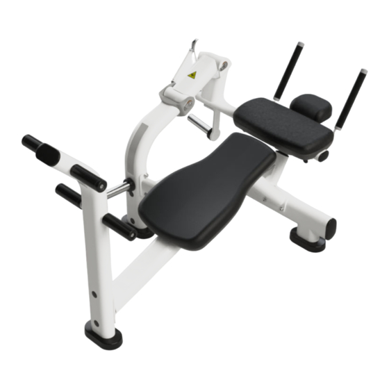
- Page 1 Life Fitness Abdominal Crunch Bench LBR-AC Assembly Instructions 1024341-0001 REV AB...
- Page 3 10601 W Belmont Ave, Franklin Park, IL 60131 • U.S.A. 847.288.3300 • FAX: 847.288.3703 Service phone number: 800.351.3737 (toll-free within U.S.A., Canada) Global Website: www.lifefitness.com International Offices AMERICAS EUROPE, MIDDLE EAST, and AFRICA (EMEA) All Other EMEA Countries and Distributor...
- Page 4 User and Service Documents Link https://lifefitness9512.zendesk.com/hc/en-us https://www.lftechsupport.com/web/document-library/documents Additional information is available online using the links above. أ علاه إل ر إبط باستخدإم إ لإ ن تر نت على إضافية معلومات تتوفر 点击上面的链接可在线获取更多信息。 Flere oplysninger er tilgængelige online gennem linket ovenfor. Bijkomende informatie is online beschikbaar via bovenstaande link.
-
Page 5: Table Of Contents
Life Fitness, LLC and its affiliated companies and subsidiaries. Disclaimer: Images and specifications are current as of the date of publication and are subject to change. 10601 W Belmont Ave, Franklin Park, IL 60131 • 847-288-3300 • www.lifefitness.com • 1024341-0001 AB • 2023 Page 3 of 21... -
Page 6: Safety Information
1. Safety Safety Information It is the sole responsibility of the purchaser of Life Fitness Family of Brands products to read the owner’s manual and warning labels and instruct all individuals, whether they are the end user or supervising personnel, on proper usage of the equipment. - Page 7 • Before use, examine all accessories approved for use with the Life Fitness Family of Brands equipment for damage or wear. Plate Loaded, Free Weight, and Body Weight Systems • Never exceed the load rating for any plate loaded station, body weight station, bench or other free weight device; including specific weight rod and band peg limits.
-
Page 8: Product Labels
Product Labels FCC Compliant Serial Number General Warning Page 6 of 21... -
Page 9: Label Locations
Label Locations Item Description Qty. General Warning FCC Compliant Serial Number Bolt to Floor Locations Raise foot covers to expose the bolt to floor location points. Item Description Qty. Foot Cover Page 7 of 21... -
Page 10: Assembly
2. Assembly Components Description Qty. Foot Rest Assembly Pivot Arm Base Assembly Weight Horn Assembly Work Arm Assembly Rod End Link Assembly Pivot Arm Assembly (with bearings and pivot shafts) Back Support Assembly 18 X 9 Pad Back Pad Head Pad Lower Base Assembly Work Arm Stop Assembly Cross Member Assembly... -
Page 11: Hardware
Hardware Item Description Qty. 3/8 Washer M10 Hex Nylock Nut CM/MJ Retainer 1-1/4 OD x 1/4 Spacer 1" Hole Plug 25mm Flange Bushing Bolt Retainer M6-1.1 X 12 Button Screw M6 Washer M10 X 1.5 - 25mm Hex Head Screw M10 x 1.5 x 20mm Screw M10 x 1.5 x 25mm Screw M10 x 1.5 x 70mm Screw... - Page 12 • Torque wrench Page 10 of 21...
-
Page 13: Assembly Procedure
Assembly Procedure Assemble Abdominal Crunch Bench 1. Attach the pivot arm base assembly to the lower base assembly, check for level and tighten hardware to 20-25 ft-lbs (27-34 Nm).. Item Description Qty. Pivot Arm Base Assembly Lower Base Assembly M10 x 1.5 x 25mm Screw 3/8 Washer M10 Hex Nylock Nut 2. - Page 14 4. Attach the foot rest assembly to the base frame, check for level and tighten hardware to 20-25 ft-lbs (27-34 Nm).. Item Description Qty. Foot Rest Assembly M10 Hex Nylock Nut 3/8 Washer M10 x 1.5 x 25mm Screw 5. With the pivot arm assembly's square-stop facing the pivot arm base assembly, attach the pivot arm assembly with the pivot shaft to the pivot arm base assembly and tighten hardware to 20-25 ft-lbs (27-34 Nm).
- Page 15 7. Attach the rod end link assembly to the pivot arm assembly and work arm assembly, then tighten hardware to 20-25 ft-lbs (27-34 Nm).. Item Description Qty. M10 x 1.5 x 25mm Screw 3/8 Washer Rod End Link Assembly Work Arm Assembly Pivot Arm Assembly 8.
- Page 16 10. Attach the weight horn assembly to the work arm assembly, then tighten hardware to 20-25 ft-lbs (27-34 Nm).. Item Description Qty. Work Arm Assembly Weight Horn Assembly 3/8 Washer M10 x 1.5 x 20mm Screw 11. Install the head pad and 18 X 19 pad onto the work arm assembly, then tighten hardware to 40-50 in-lbs (4.5-5.6 Nm).
- Page 17 13. Gently tap 1" hole plugs into place. Item Description Qty. 1" Hole Plug 14. If desired, peel and stick label from the multi-language general warning sheet and carefully place over the English (default) label. Item Description Qty. Multi-Language General Warning Sheet Page 15 of 21...
-
Page 18: Product Information
3. Product Information Specifications Machine Weight: 168 lbs. 76 kg. Size (L x W x H): in. = 64 x 36 x 40 cm = 163 x 92 x 101 Live Area (L x W): in. = 112 x 72 cm = 285 x 183 Max User Weight: 300 lbs. -
Page 19: Bolt To Floor Guide Introduction
4. Bolt to Floor Guide Introduction Life Fitness Family of Brands designs its products to be stable when used as designed. Because strength training is dynamic, we cannot predict how users will ultimately use the products in all circumstances. Therefore, Life Fitness Family of Brands recommends that strength training equipment be secured to a solid, level surface to stabilize and eliminate rocking or tipping over. -
Page 20: Anchor Type - Static
Anchor Type - Static Static Anchor Standard Sizes Drill Bit Size Imperial: KH-EZ 3/8" x 5" 3/8in Metric: HUS-H 10mm x 130mm 10mm Anchor Specifications Static Anchor Minimum Concrete Minimum Drill Depth Minimum Concrete Minimum concrete Thickness in Concrete Embedment compressive strength KH-EZ 1/4”... -
Page 21: Static Anchor Procedure
• Vacuum (for debris) Static Anchor • Floor scanner / rebar detector (optional) • 1” L-shape SDS rotary hammer • 1/4" x 12" (6mm x 305mm) carbide drill bit (for 1/4” (6mm) anchors) • 3/8" x 12" (8mm x 305mm) carbide drill bit (for 3/8” (8mm) anchors) •... - Page 22 4. Insert fastener and tighten to 18 Foot-Pounds (24Nm) for 1/4” (6mm) anchor or 40 Foot-Pounds (54Nm) for 3/8” (8mm) anchor. NOTE: If the legs/frame do not contact the mounting surface DO NOT pull down with the fastener or anchor. Loosen frame hardware and re-tighten to allow machine to align.
-
Page 23: Foot Dimensions
Foot Dimensions Use below image to determine foot specifications. Page 21 of 21...
Need help?
Do you have a question about the LBR-AC and is the answer not in the manual?
Questions and answers