
Related Manuals for LifeFitness G5


Summary of Contents for LifeFitness G5
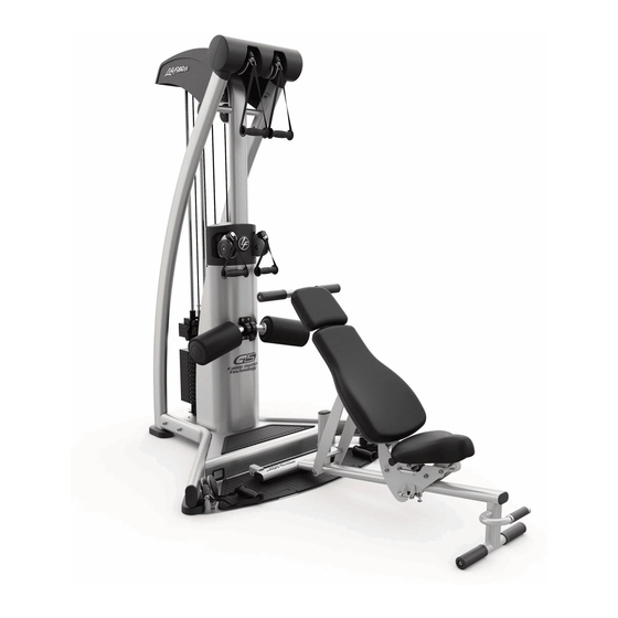
- Page 1 G5 CABLE MOTION TECHNOLOGY GYM SYSTEM USER GUIDE WARNING: Read and follow all directions for each step to insure proper assembly of this product. CLASS H PART # LEA7767401 REV. A VERSION: LFG5-101 DATE: 07-01-04...
- Page 2 DO NOT securely tighten any frame connections until the entire frame has been assembled, unless otherwise stated. NOTE: In a continual effort to improve our products, specifications are subject to change © 2004 Life Fitness, a division of Brunswick Corporation. All rights reserved. Life Fitness is a trademark of Brunswick Corporation www.LifeFitness.com...
- Page 3 GYM DIMENSIONS...
- Page 4 PTD A SSY , TOP PULLEY S LEA7761701 PTD A SSY , FRONT SHROUD LEA7761601 PTD A SSY , G5, TOP SHROUD LEA776240 PTD A SSY , HEA D PLA TE PULLEY LEA7754501 PTD A SSY , FLOA TING PULLEY S LEA6925501 PTD A SSY , HEA D PLA TE 20"...
- Page 5 EXPLODED VIEW...
- Page 6 HARDWARE: REQUIRED TOOLS: * 9/16” wrench * Ratchet and 9/16” socket * Adjustable wrench * Tape measure * Two 8mm Allen wrenches BOLT LENGTH...
- Page 7 FIGURE 1 STEP 1: LOOSELY assemble bottom LEFT UPRIGHT (4) and RIGHT UPRIGHT (5) to FRONT UPRIGHT (1) using four 3/8 x 3-1/2 BOLTS (34), eight 3/8 WASHERS (28) and four 3/8 NUTS (33) and TOP PULLEYS (7) LOOSELY assemble upper LEFT FRAME (4) and RIGHT FRAME (5) to FRONT UPRIGHT (1) and TOP PULLEYS (11), using four 3/8 x 3/4 BOLTS (31), four 3/8 WASHERS (28) as illustrated in FIGURE 1 NOTE: THE TOP PULLEY WELDMENT ATTACHES TO THE INSIDE OF THE UPRIGHT SIDES AND THE ORIENTATION S...
- Page 8 FIGURE 2 STEP 2: LOOSELY attach FOOT PLATE (2) to front of FRONT UPRIGHT (1) using two 3/8 x 3/4 BOLTS (31), and two 3/8 WASHERS (28). LOOSELY attach the FOOT PLATE (2) to the sides of UPRIGHTS (4) and (5) using two 3/8 x 3-1/2 BOLTS (34) and two 3/8 WASHERS (28)
- Page 9 TIGHTEN SECURLEY FIGURE 3 STEP 3: Insert two BUSHINGS (30) into bottom of FRONT UPRIGHT (1), slide one CUSHION (24) to bottom of each GUIDE ROD (22) and insert both GUIDE RODS (22) thru BUSHING GUIDES (30) and holes located at bottom of FRONT UPRIGHT (1) CAREFULLY slide HEAD PLATE (12) over top of GUIDE RODS (22) followed by two BUMPER (36), two COLLARS (21), two BUSHINGS (30) and position BRACKET (6) over top of GUIDE RODS (22) CAREFULLY slide guide rod assembly under top FRONT UPRIGHT (1) and place TOP SHROUD (9) over top of...
- Page 10 FIGURE 4 STEP 4 Taking one end of UPPER (SHORT) CABLE (43) insert thru top front pulley and follow routing illustration to HEAD PLATE PULLEY (10) and continue to other side ending at the other top front pulley. CABLE MUST BE INSERTED BETWEEN PULLEY AND PULLEY GUIDES AND MOVE FREELY...
- Page 11 FIGURE 5 STEP 5: Insert ball end of GUIDE CABLE (42) through eye hook on FLOATING PULLEY BRACKET (11), insert and hook ball end of cable into bottom of frame. Screw threaded end of cable into the FRONT UPRIGHT (1) and tighten until cable is taught, Tighten JAM NUT securely REPEAT ABOVE PROCESS FOR OTHER GUIDE CABLE (42)
- Page 12 FIGURE 6 STEP 6: Insert LOWER (LONG) CABLE (44) through pulley 1 and begin routing cable to next sequential number finishing at low Take other LOWER (LONG) CABLE (44) and follow same process for other side. CABLE MUST BE INSERTED BETWEEN PULLEY AND PULLEY GUIDE AND MOVE FREELY...
- Page 13 ITEM QTY. PART NO. DESCRIPTION LEA7726201 COUPLER, QUICK CONNECT LEA7726401 HSNG, QUICK CONNECT LEA7726301 SLEEVE, QUICK CONNECT LEA3249901 SPRING, COMPRESSION LEA3250002 M5 X 0.8 HXS SOC CS ST BZ X 8 FIGURE 7 STEP 7: USE THIS ASSEMLY AT THE END OF EACH CABLE Slide each item onto cable as follows: ITEM 1, ITEM 2, ITEM 3, and insert cable end into ITEM 4.
- Page 14 FIGURE 8 STEP 8 Attach FRONT SHROUD (8) using two 3/8 X 3-1/2 SCREWS and two 3/8 WASHERS (28) Attach REAR BOTTOM PLATE (13) using two 10-32 X ½ SCREW...
- Page 15 FIGURE 9 STEP 9: Insert two FLANGE BEARINGS (23) and one SHAFT (32) into center hole of ROUND INDEXTER Attach ROLLER PAD ASSEMBLY (3) to center hole of ROUND INDEXTER and attach using two 3/8 WASHERS (28) and two 3/8 X 1/4 BOLTS (31) and tighten firmly allowing ROLLER PAD ASSEMBLY (3) to move freely.
- Page 16 FIGURE 10 STEP 10: Attach TOP COVER (15) using four METAL SCREWS (25) as shown in illustration ITEM 25 MUST BE INSTALLED BEFORE ITEM 26. Attach FRONT (17) and BACK COVER (16) to each other using six PLASTIC SCREWS (26). Attach FRONT (17) and BACK COVER (18) to UPRIGHT SIDES (4), (5) using four METAL SCREWS (25) Attach FRONT and BACK MID COVERS (18), (19) to each other using four PLASTIC SCREWS (26) as shown in illustration.
- Page 17 FIGURE 11 STEP 11: Referencing step 7, push back on ITEM (3) at end of cable and attach SHORTER HANDLES (38) to top of frame. Repeat process for attaching the ADJUSTABLE HANDLES (40 ) to the lower cable ends and the medium handles (39) to the middle ends. NOTE: THIS IS THE HANDLE CONFIGURATION THAT IS USED FOR MOST EXERCISES.
- Page 18 YOU MAY NEED SERVICE YOU WILL BE ASKED FOR THIS INFORMATION. REMEMBER TO FILL OUT YOUR WARRANTY REGISTRATION CARD AND MAIL BACK. MODEL #________________________ SERIAL #_________________________ DATE OF PURCHASE: _____________ DEALERS NAME: _________________ DEALERS PHONE #_______________ Thank you for purchasing the Life Fitness G5 CABLE MOTION GY SYSTEM...
- Page 19 LIMITED WARRANTY Life Fitness extends the following LIMITED WARRANTY to the original owner of the Life Fitness product. The Warranty terms apply to IN HOME and LIGHT INSTITUTIONAL USE ONLY. 1. LIMITED WARRANTY ON FRAME AND WELDS. If the frame of the Life Fitness product or a weld should crack or break, it will be repaired or replaced by Life Fitness.
- Page 20 LIFE FITNESS 5100 NORTH RIVER ROAD. SCHILLER PARK, IL 60176 U.S.A. Tel: 1.847.288.3300 Fax: 1.800.216.8893 1.800.328.9714 (Toll-free within the U.S. and Canada) www.LifeFitness.com INTERNATIONAL OFFICES Life FitnessAtlantic BV Life Fitness (UK) Ltd. Atlantic Headquarters Queen Adelaide Bijdorpplein 25-31 Ely, Cambs CB7 4UB...
Need help?
Do you have a question about the G5 and is the answer not in the manual?
Questions and answers