
Related Manuals for Advantech ASMB-927 Series


Summary of Contents for Advantech ASMB-927 Series
- Page 1 User Manual ASMB-927 Series ® Dual LGA4677 4th Gen Intel ® Xeon Scalable EATX Server Board with 16 DDR5, 4 PCIe x16, 9 SATA 3.0, 6 USB 3.2 (Gen1), Dual 10GbE, and IPMI...
- Page 2 No part of this manual may be reproduced, copied, translated, or transmitted in any form or by any means without the prior written permission of Advantech Co., Ltd. The information provided in this manual is intended to be accurate and reliable.
- Page 3 Advantech has come to be known. Your satisfaction is our primary concern. Here is a guide to Advantech’s cus- tomer services.
- Page 4 Initial Inspection Before installing motherboard, please make sure that the following materials have been shipped: 1 x ASMB-927 Startup Manual 1 x SATA data cable 1 x SATA power cable 2 x CPU power cables (8P) 2 x CPU carriers ...
-
Page 5: Table Of Contents
Contents Chapter Overview..........1 Introduction ....................2 Features ....................2 Specifications .................... 3 Table 1.1: Specifications ............. 3 Board Layout, Jumpers, and Connectors..........5 Figure 1.1 Board Layout .............. 5 Figure 1.2 Rear I/O ..............5 Table 1.2: Onboard LAN LED color definition ......6 Table 1.3: Jumpers.............. - Page 6 2.25 NVMe RAID LED Control (PEHP1)............28 Chapter BIOS..........29 Introduction ..................... 30 BIOS Setup ..................... 31 3.2.1 Main Menu .................. 31 3.2.2 Advanced BIOS Features Setup..........32 3.2.3 Platform Configuration ..............53 3.2.4 Socket Configuration ..............63 3.2.5 Server Management ..............75 3.2.6 Security..................
- Page 7 REAR_FAN).................... 97 Table B.7: CPU FAN connector (CPUFAN0~1)......97 Table B.8: SYS FAN connector (SYSFAN0~3, REAR_FAN) ..97 Power LED (JFP3) .................. 97 Table B.9: Power LED connector (JFP1)........97 External Speaker Connector (JFP2) ............98 Table B.10:External speaker connector (JFP2) ......98 B.10 Reset Connector (JFP1) .................
- Page 8 ASMB-927 User Manual viii...
-
Page 9: Chapter 1 Overview
Chapter Overview... -
Page 10: Introduction
Introduction The ASMB-927 serverboard is the most advanced 4th Gen Intel Xeon Scalable series board for industrial and medical equipment, as well as HPC applications that require high-performance computing power and multi-expansion slots. This server- board supports the 4th Gen Intel Xeon Scalable series processor and DDR5 RDIMM 4800MHz memory up to 4TB. -
Page 11: Specifications
Specifications Table 1.1: Specifications Processor Dual Intel LGA4677 Xeon processor sockets Supports 4th Gen Intel Xeon scalable family, up to 60 cores Supports the TDP of processor up to 225 W (please consider extended air thermal solution while using CPU> 205 W TDP) System Memory Total Slots 16 (1 DIMM per channel) - Page 12 Table 1.1: Specifications Expansion Slots 4 x PCIe Gen5 X16 slots – Slot 1: PCIe X16 slot, signal from CPU0, CXL support – Slot 3: PCIe X16 slot, signal from CPU0, CXL support – Slot 5: PCIe X16 slot, signal from CPU0, CXL support PCI Express –...
-
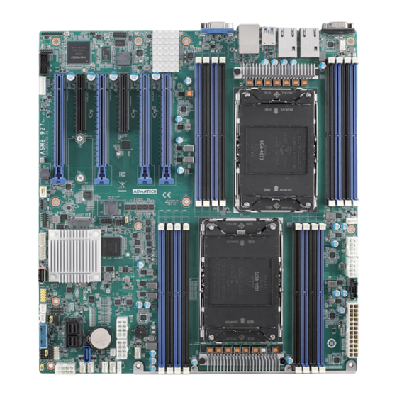
Page 13: Board Layout, Jumpers, And Connectors
Board Layout, Jumpers, and Connectors USB3C1 PCIEX16 PCIEX8 PCIEX16 PCIEX16 PCIEX16 PCIEX8 BMC_LAN VGA1 LAN2 COM1 LAN1 _SLOT3 _SLOT4 _SLOT5 _SLOT6 _SLOT1 _SLOT2 USB3C2 REAR_FAN HDAUD1 BMC_SPI1 COM2 KBMS1 DIMML1 DIMMK1 DIMMJ1 DIMMI1 DIMMM1 JME1 JCMOS1 DIMMN1 BIOS_SKT1 DIMMO1 DIMMP1 EC_SKT1 CPU1 PSON1... - Page 14 Table 1.2: Onboard LAN LED color definition 100 Mbps/1 Gbps/10 Gbps LAN Link/Activity LED Scheme LAN1 & LAN 2 Left LED Right LED Link 100 Mbps Active Link Amber Green 1 Gbps Active Amber Blinking green Link Green Green 10 Gbps Active Green Blinking green...
- Page 15 Table 1.4: Connectors Label Function ATXPWR1 ATX 24-pin main power connector ATX12V1, ATX12V3 Processor power connector (mandatory) ATX12V2, ATX12V4 Processor power connector (reserved) For optional battery kit BIOS_SKT1 BIOS SPI ROM BMC_SPI1 BMC SPI ROM BMC_LAN IPMI dedicated LAN connector COM1 RS-232 connector COM2...
-
Page 16: Block Diagram
Table 1.4: Connectors SYSFAN0~SYSFAN3, System FAN connector REAR_FAN SYS_LED1 System LED connector USB2H1 USB 2.0 port (9-pin header) USB2A1 USB 2.0 port (Type-A) USB3C1, USB3C2, USB 3.2 port 1, 2(rear I/O); USB 3.2 port 3, 4(rear I/O); USB 3.2 USB3H1 port 5, 6 (20-pin header) VGA1 VGA connector... -
Page 17: System Memory
System Memory The ASMB-927 has 16 288-pin memory slots for DDR5 3200/3600/4000/4400/4800 MHz memory modules with a maximum capacity of 4TB (maximum 256GB for each DIMM). The ASMB-927 supports registered DIMM memory modules. Memory Installation Memory performance is affected by different DIMM configurations. To reach optimal memory interleaving, be sure to install identical DIMM types with the same size, speed, and number of ranks on those memory slots corresponding to the correct pro- cessor. - Page 18 Table 1.7: DIMM configuration with dual CPUs Channel Quantity memory installed Note! 1, 3, 5, 7, 9, 11, 13, 15 DIMMs are not recommended DIMM slots when dual CPUs are installed. ASMB-927 User Manual...
-
Page 19: Processor Installation
Processor Installation The ASMB-927 is designed for the Intel Xeon processor scalable family. Remove dust cover. Install CPU on CPU clip and align with pin 1 mark. ASMB-927 User Manual... - Page 20 Install the CPU clip assembly on the heatsink as a processor + heatsink module. Put the processor heatsink module into the motherboard bolster plate by using a T-30 screwdriver (follow heatsink label directions 1 to 4). For best durability, 8.0 in-lbf torque is recommended.
-
Page 21: Chapter 2 Connections
Chapter Connections... -
Page 22: Introduction
Introduction You can access most of the connectors from the top of the board as it is being installed in the chassis. If you have a large number of cards installed, you may need to partially remove a card to make all the connections. USB Ports and LAN Port The USB ports comply with USB 2.0 and USB 3.2 Gen1. -
Page 23: Vga Connector (Vga1)
VGA Connector (VGA1) The ASMB-927 includes a VGA interface that can drive conventional CRT and LCD displays. VGA1 Serial Ports (COM1~2) The ASMB-927 offers one serial port on the rear plate and one 2.50mm onboard with 2 x 5-pin pitches. COM1 COM2 COM1... -
Page 24: Ps2 Keyboard And Mouse Connectors (Kbms1)
PS2 Keyboard and Mouse Connectors (KBMS1) The 6-pin KBMS1 connector is for additional keyboard & mouse device usage. KBMS1 KBMS1 CPU Fan Connector (CPUFAN0~1) If a fan is used, this connector supports cooling fans that draw up to 1.5A (18 W). CPUFAN1 CPUFAN0~1 CPUFAN0... -
Page 25: System Fan Connector (Sysfan0~3, Rear_Fan)
System Fan Connector (SYSFAN0~3, REAR_FAN) SYSFAN0~3 REAR_FAN Front Panel Connector (JFP1, JFP2, JFP3) There are several external switches and LEDs to monitor and control the ASMB-927. ASMB-927 User Manual... -
Page 26: Power Led (Jfp3)
2.8.1 Power LED (JFP3) JFP3 pins 1 and 3 are for the power LED. Refer to Appendix B for detailed informa- tion on the pin assignments. If an ATX power supply is used, the system’s power LED status will be as indicated. Table 2.1: ATX power supply LED status ACPI Power Mode LED (ATX power) -
Page 27: Case Open (Jcase1)
Case Open (JCASE1) A chassis intrusion header is located at JCASE1 on the motherboard. Attach the appropriate cable from the chassis to be informed of a chassis intrusion when the chassis has been opened. The default function is disabled and pin 1-2 is bridged by a jumper cap. -
Page 28: Front Panel Lan Indicator Connector (Lanled1)
2.11 Front Panel LAN Indicator Connector (LANLED1) LANLED1 2.12 SATA and sSATA (SATA 0~3, SATA 4~7) The ASMB-927 features eight SATA III ports (6 Gbps) via SFF-8643 connectors and one 7-pin SATA port. sSATA ASMB-927 User Manual... -
Page 29: Connector (M2_2280_2)
2.13 M.2 Connector (M2_2280_2) The M.2 2280 connector supports both SATA and PCIe SSD components. M2_2280_2 ASMB-927 User Manual... -
Page 30: Pcie Expansion Slots
2.14 PCIe Expansion Slots The ASMB-927 provides six expansion slots that can support up to three double- deck cards (with chassis HPC-7485). The riser card for 1U or 2U chassis can be used in slot 6 only, and the PCIe link is from CPU1. Table 2.2: PCIe slots Slot length Link... -
Page 31: Auxiliary Power Connector (Atxpwr1/Atx12V1/Atx12V2/Atx12V3/ Atx12V4)
2.15 Auxiliary Power Connector (ATXPWR1/ ATX12V1/ATX12V2/ATX12V3/ATX12V4) Note! Please use a power supply of SSI type; minimum output should be at least 700 W with 5 Vsb @2.5 A. The ATXPWR1 & ATX12V1 & ATX12V3 should be all connected with the power supply, otherwise the ASMB-927 will not boot up normally. -
Page 32: Pcie Power Connector (Slot12V1)
This SLOT12V1 connector is only necessary if PCIe cards that draw more than 70 watts from the PCIe bus are installed on the motherboard. 2.17 HD Audio Interface Connector (HDAUD1) The ASMB-927 has one audio connector for Advantech's audio board (P/N: PCA- AUDIO-HDB1E) installation. HDAUD1 ASMB-927 User Manual... -
Page 33: Espi Connector (Espi1)
2.18 ESPI Connector (ESPI1) ESPI1 2.19 CMOS Clear and ME Update Connector (JCMOS1, JME1) Setting jumpers from pin 1-2 to pin 2-3, then back to pin 1-2 to reset CMOS data and enable ME update. JME1 JCMOS1 ASMB-927 User Manual... -
Page 34: Pmbus Connector (Pmbus1)
2.20 PMBUS Connector (PMBUS1) 2.21 Front Panel SMBUS Connector (SMBUS1) SMBUS1 ASMB-927 User Manual... -
Page 35: Bmc Ic Socket (Bmc_Spi1)
2.22 BMC IC Socket (BMC_SPI1) Enabling IPMI feature through BMC_SPI1. The BMC image has already been pre- installed on ASMB-927. 2.23 GPIO Connector (GPIO1) GPIO1 ASMB-927 User Manual... -
Page 36: Intel Virtual Raid (Vroc1)
2.24 Intel Virtual RAID (VROC1) The Intel VROC license key of VMD allows NVMe SSDs to connect via PCIe and directly manage the CPU for better RAID performance. Enable NVMe SSD RAID, hot-plug, and LED management features via VROC connector. VROC1 2.25 NVMe RAID LED Control (PEHP1) -
Page 37: Ami Bios
Chapter AMI BIOS... -
Page 38: Introduction
Introduction With the AMI BIOS setup program, you can modify BIOS settings and control the special features of your computer. The setup program uses a number of menus for making changes and turning special features on or off. This chapter describes the basic navigation of the ASMB-927 setup screens. -
Page 39: Bios Setup
BIOS Setup 3.2.1 Main Menu Press <Del> during bootup to enter the AMI BIOS CMOS setup utility; the main menu will appear on the screen. Use arrow keys to select among the items and press <Enter> to accept or enter the sub-menu. The Main BIOS setup screen has two main frames. -
Page 40: Advanced Bios Features Setup
3.2.2 Advanced BIOS Features Setup Select the advanced tab from the ASMB-927 setup screen to enter the advanced BIOS setup screen. You can select any of the items in the left frame of the screen, such as CPU configuration, to go to the sub menu for that item. You can display an advanced BIOS setup option by highlighting it using the arrow keys. - Page 41 3.2.2.1 Trusted Computing Security Device Support Enables or disables BIOS support for security devices. ASMB-927 User Manual...
- Page 42 3.2.2.2 ACPI Settings Lock Legacy Resources Enable or disable the lock legacy resources feature. ASMB-927 User Manual...
- Page 43 3.2.2.3 Redfish Host Interface Settings Redfish Enable or disable the BMC Redfish feature. 3.2.2.4 IT5121E Super IO Configuration ASMB-927 User Manual...
- Page 44 Serial Port 1 Configuration – Serial Port Enable or disable serial port 1. – Change Settings To select an optimal setting for serial port 1. Default setting is "Auto". ASMB-927 User Manual...
- Page 45 Serial Port 2 Configuration – Serial Port Enable or disable serial port 2. – Change Settings To select an optimal setting for serial port 2. Default setting is "Auto". ASMB-927 User Manual...
- Page 46 3.2.2.5 IT5121E HW Monitor Watchdog Timer Enable or disable the watchdog timer function. CPU ACPI Shutdown Temperature Enable or disable the ACPI shutdown temperature threshold. When the system reaches the shutdown temperature, it will be automatically shut down by the ACPI OS to protect the system from overheat damage.
- Page 47 ASMB-927 User Manual...
- Page 48 3.2.2.6 Serial Port Console Redirection Serial Communication via IPMI COM ASMB-927 User Manual...
- Page 49 COM1 Console Redirection Settings – Terminal Type Select a terminal type to be used for console redirection. Options available: VT100 / VT100+ / ANSI / VT-UTF8. – Bits Per Second Select the baud rate for console redirection. Options available: 9600 / 19200 / 38400 / 57600 / 115200. –...
- Page 50 – VT-UTF8 Combo Key Support Enable VT-UTF8 combination key support for ANSI/VT100 terminals – Recorder Mode When this mode enabled, only text will be sent; this is to capture terminal data. Options available: Enabled/Disabled. – Resolution 100 x 31 Enables or disables the extended terminal resolution. –...
- Page 51 Console Redirection Settings – Out-of-Band Mgmt Port To select the com port user would like to set for having console redirection feature. – Terminal Type Set as "VT100", "VT100+", "VT-UTF8", or "ANSI". "VT-UTF8" is the default setting. – Bits Per Second To select serial port transmission.
- Page 52 3.2.2.7 PCI Subsystem Settings Above 4G Decoding Enable or disables 64-bit capable devices to be decoded in above 4G address space (only if system supports 64-bit PCI decoding). Note! Some graphics or GPU cards need to enable 4G decoding. ASMB-927 User Manual...
- Page 53 3.2.2.8 USB Configuration Legacy USB Support This is for supporting USB device under a legacy OS such as DOS. When choosing "Auto", the system will automatically detect if any USB device is plugged into the computer and enable USB legacy mode when a USB device is plugged, or disable USB legacy mode when no USB device is attached.
- Page 54 XHCI Hand-off This is a workaround for OS without XHCI hand-off support. The XHCI owner- ship change should be claimed by XHCI driver. "Enabled" is the default setting. USB Mass Storage Driver Support Enable or disable USB mass storage driver support. USB Transfer Time-Out ...
- Page 55 Device Reset Time-Out Selects the USB device reset time-out value. [10, 20, 30, 40 seconds] ASMB-927 User Manual...
- Page 56 Device Power-up Delay This item appears only when the device power-up delay item is set to [manual]. "Auto" is the default setting. Mass Storage Devices Default is "Auto" to enumerate mass storage devices according to media format. ASMB-927 User Manual...
- Page 57 3.2.2.9 Network Stack Configuration Network Stack Enable or disable UEFI network stack. ASMB-927 User Manual...
- Page 58 3.2.2.10 CSM Configuration CSM Support Enable or disable UEFI CSM (Compatibility Support Module) to support a leg- acy PC boot process. GateA20 Active This items is useful when RT code is executed above 1MB. When it's set as "Upon Request"...
- Page 59 Option ROM Messages Use "Force BIOS or keep current" to set the display mode for option ROM. Boot Option Filter Change UEFI/legacy ROM priority for boot option. "UEFI and Legacy" is the default setting. ASMB-927 User Manual...
- Page 60 Network Control the execution of UEFI and legacy PXE OpROM. Storage Control the execution of UEFI and legacy storage OpROM. Video Control the execution of UEFI and legacy video OpROM. Other PCI Devices Control the execution of UEFI and legacy other PCI devices OpROM. ASMB-927 User Manual...
-
Page 61: Platform Configuration
3.2.3 Platform Configuration 3.2.3.1 PCH Configuration ASMB-927 User Manual... - Page 62 PCH Devices This item is to set up IO controller hub devices. ASMB-927 User Manual...
- Page 63 Restore AC Power Loss Specify what state to go to when power is re-applied after a power failure (G3 state). It can be set to "Power on", "Power Off", and "Last State" states. – Case Open Warning Enable or disable the chassis intrusion monitoring function. When enabled and the case is opened, the warning message will show in POST screen.
- Page 64 – VGA Priority Determines priority between onboard and 1st off-board video device found. "Auto" is the default setting. – Onboard VGA Controller Enable or disable onboard VGA controller. – RTC Wake System from S5 Enable or disable system wake on alarm event. ASMB-927 User Manual...
- Page 65 PCI Express Configuration – M.2 PCIe Slot Root Port PCIe root port settings. ASMB-927 User Manual...
- Page 66 SATA RST Configuration ASMB-927 User Manual...
- Page 67 ASMB-927 User Manual...
- Page 68 – SATA Configuration Enable or disable SATA devices. – SATA Mode Selection Set as AHCI or RAID when SATA controllers are enabled. – Support ALPM Enable or disable Aggressive Link Power Management (ALPM) protocol for Advanced Host controller Interface-compliant (AHCI) Serial ATA (SATA) devices.
- Page 69 USB Configuration Enable/disable this USB physical connector (physical port). Once disabled, any USB devices plugged into the connector will not be detected by BIOS or OS. ASMB-927 User Manual...
- Page 70 Networking – LAN Controller Enable or disable Intel X710 controller support. – LAN1 PXE OpROM Enable or disable boot option for Intel X710 controller. – LAN2 PXE OpROM Enable or disable boot option for Intel X710 controller. ASMB-927 User Manual...
-
Page 71: Socket Configuration
3.2.3.2 Server ME Configuration This page shows the server ME configuration information. 3.2.4 Socket Configuration ASMB-927 User Manual... - Page 72 3.2.4.1 Processor Configuration Per-Socket Configuration Use this to select how many processor cores you want to activate when you are using a dual or quad core processor. ASMB-927 User Manual...
- Page 73 Hyper-Threading [All] Enable or disable Intel Hyper Threading technology. Hardware Prefetcher Hardware Prefetcher is a technique that fetches instructions and/or data from memory into the CPU cache memory well before the CPU needs it, so that it can improve the load-to-use latency.
- Page 74 3.2.4.2 Uncore General Configuration Uncore Status Display information of Intel UltraPath Interconnect (UPI). ASMB-927 User Manual...
- Page 75 Link Speed Mode Select the UPI link speed as either fast mode or slow mode. Link Frequency Select Allows for selecting the UPI link frequency. – Link L0p Enable Enable or disable UPI Link0p. "Auto" is the default setting. –...
- Page 76 3.2.4.3 Memory Configuration Numa Enable or disable non uniform memory access (NUMA). The Numa function is used by dual CPUs. Memory Technology Display memory topology with DIMM population information. ASMB-927 User Manual...
- Page 77 3.2.4.4 IIO Configuration Socket0 PCIe Configuration PCIe port bifurcation control and select target link speed as Gen1, Gen2, Gen3,Gen4, or Gen5. "Auto" is the default setting. ASMB-927 User Manual...
- Page 78 Socket1 PCIe Configuration PCIe port bifurcation control and select target link speed as Gen1, Gen2, Gen3, Gen4, or Gen5. "Auto" is the default setting. ASMB-927 User Manual...
- Page 79 Intel VT for Directed I/O (VT-d) Enable or disable Intel Virtualization Technology for directed I/O. ASMB-927 User Manual...
- Page 80 PCI-E ASPM Support (Global) Sets the ASPM level to disable or per-port. 3.2.4.5 Advanced Power Management Configuration ASMB-927 User Manual...
- Page 81 CPU P State Control ASMB-927 User Manual...
- Page 82 Package C State Control ASMB-927 User Manual...
-
Page 83: Server Management
3.2.5 Server Management Wait for BMC If enabled, motherboard will wait 30 ~ 60 seconds until BMC module boots up completely. After that, the normal BIOS post screen will be displayed. If disabled, motherboard will not wait for BMC module's response. Wait for BMC counter ... - Page 84 3.2.5.1 System Event Log SEL Components Enable or disable all features of system event logging during boot. Erase SEL Choose options for erasing SEL. "No" is the default setting. Log EFI Status Codes Disable the logging of EFI status codes or log only error code or only progress code or both.
- Page 85 3.2.5.2 BMC Self Test Log Erase Log Erase log options. When Log Is Full Select the action to be taken when log is full. ASMB-927 User Manual...
- Page 86 3.2.5.3 BMC Network Configuration Configuring Address Source Select to configure LAN channel parameters statically or dynamically (by BMC). Unspecified options will not modify any BMC network parameters during BIOS phase. 3.2.5.4 BMC Sensor Event Configuration ASMB-927 User Manual...
-
Page 87: Security
3.2.6 Security Note! With AC power & Battery. Short CMOS1 Jumper: Date/Time & Password: Keep Setting: reset to default AC power and CMOS battery are removed. Short CMOS1 Jumper: Date/Time: reset to default Password: Keep Setting: reset to default ASMB-927 User Manual... - Page 88 3.2.6.1 Secure Boot ASMB-927 User Manual...
-
Page 89: Boot
3.2.7 Boot Setup Prompt Timeout Number of seconds to wait for setup activation key. "1" is the default setting. Bootup NumLock State Select the keyboard NumLock state as "On" or "Off". Quiet Boot Enable or disable quiet boot option. Boot Option Priorities ... -
Page 90: Save & Exit
3.2.8 Save & Exit Save Changes and Exit Exit system setup after saving the changes. Discard Changes and Exit Exit system setup without saving any changes. Save Changes and Reset Reset the system after saving changes. Discard Changes and Reset ... -
Page 91: Chipset Software Installation Utility
Chapter Chipset Software Installation Utility... -
Page 92: Before Beginning
To facilitate the installation of the enhanced display drivers and utility software, read the instructions in this chapter carefully. The drivers for the ASMB-927 are available online for download from the Advantech support website. Before beginning, it is important to note that most display drivers need to have the relevant software application already installed on the system prior to installing the enhanced display drivers. -
Page 93: Graphics Setup
Chapter Graphics Setup... -
Page 94: Introduction
Introduction Install the ASPEED VGA driver to enable this function, which includes the following features: 32-bit 2D graphics engine on board for normal use. 64 MB RAM for this chip, the highest resolution is 1920x1200. Windows Series Driver Setup When the folder is displayed, navigate to the “Graphic”... -
Page 95: Lan Configuration
Chapter LAN Configuration... -
Page 96: Lan Configuration
LAN Configuration 6.1.1 Introduction The ASMB-927 has two ten Gigabit Ethernet LAN connections, LAN1 and LAN2 - ® Intel X710-AT2. They eliminate bottlenecks of network data flow and incorporate Gigabit Ethernet at 10 Gbps. 6.1.2 Features 100/1000 & 10G Base-T Ethernet controller ... -
Page 97: Appendix A Programming The Watchdog Timer
Appendix Programming the Watchdog Timer... -
Page 98: Watchdog Timer Overview
The ASMB-927’s watchdog timer can be used to monitor system software operation and take corrective action if the software fails to function within the programmed period. This section describes the operation of the watchdog timer and how to pro- gram it. Watchdog Timer Overview The watchdog timer is built in to the EC controller IT5121VG. -
Page 99: Programming The Watchdog Timer
Programming the Watchdog Timer The I/O port address of the watchdog timer is as below: Table A.1: Adsresses Address Description 0x57 Event - Warm Reset: 0x04 0x5E Warm Reset Timer (High BYTE) Based 100ms 0x5F Warm Reset Timer (Low BYTE) Here is an example to step by step program the Watchdog Timer. - Page 100 ASMB-927 User Manual...
-
Page 101: Appendix B I/O Pin Assignments
Appendix I/O Pin Assignments... -
Page 102: Usb2.0 Header (Usb2H1)
USB2.0 Header (USB2H1) Table B.1: USB Header (USB2_78, USB2_910) Signal Signal USB_VCC5 USB_VCC5 USB_D- USB_D- USB_D+ USB_D+ USB 3.2 Gen1 Header (USB3H1) Table B.2: USB Header (USB5_6, USB7_8) Signal Signal +5 V STDA_SSRX- STDA_SSRX+ STDA_SSTX- STDA_SSTX+ STDA_SSTX+ STDA_SSTX- STDA_SSRX+ STDA_SSRX- +5 V ASMB-927 User Manual... -
Page 103: Vga Connector (Vga1)
VGA Connector (VGA1) Table B.3: VGA Connector (VGA1) Signal Signal GREEN BLUE H-SYNC V-SYNC RS-232 Interface (COM1) Table B.4: RS-232 Connector (COM1) Signal ASMB-927 User Manual... -
Page 104: Interface (Com2)
RS-232 Interface (COM2) Table B.5: RS-232 header (COM2) Signal External Keyboard Connector (KBMS1) Table B.6: External keyboard connector (KBMS2) Signal KB CLK KB DATA MS DATA MS CLK ASMB-927 User Manual... -
Page 105: System & Cpu Fan Power Connector
System & CPU Fan Power Connector (CPUFAN0~1, SYSFAN0~3, REAR_FAN) Table B.7: CPU FAN connector (CPUFAN0~1) CPUFAN0 CPUFAN1 +12 V +12 V FAN0 MODE_TACH FAN1 MODE_TACH FAN0 MODE_PWM FAN1 MODE_PWM Table B.8: SYS FAN connector (SYSFAN0~3, REAR_FAN) SYS FAN0 SYS FAN1 SYS FAN2 SYSFAN3 REAR_FAN... -
Page 106: External Speaker Connector (Jfp2)
External Speaker Connector (JFP2) 1 4 7 10 Table B.10: External speaker connector (JFP2) Function SPK+ SPK- B.10 Reset Connector (JFP1) 9 12 Table B.11: Reset connector (JFP1) Signal RESET B.11 HDD LED Connector (JFP1) Table B.12: HDD LED connector (JFP1) Signal HDD_LED+ HDD_LED-... -
Page 107: Atx Soft Power Switch (Jfp1)
B.12 ATX Soft Power Switch (JFP1) Table B.13: ATX soft power switch (JFP1) Signal PWR-BTN B.13 SMBus Connector (SMBUS1) Table B.14: Front panel SMBus connector (SMBUS1) Signal +3.3V_AUX SMB_SCL_FRU SMB_SDA_FRU ASMB-927 User Manual... -
Page 108: Usb & Lan Ports (Lan1, Lan2, Usb3C1, Bmc_Lan_Usb3C2)
B.14 USB & LAN Ports (LAN1, LAN2, USB3C1, BMC_LAN_USB3C2) Table B.15: USB port Signal Signal VCC_DUAL Data0+ Data0- Table B.16: Giga LAN 10/100/1000 Base-T RJ-45 port Signal Signal MID0+ MID2+ MID0- MID2- MID1+ MID3+ MID1- MID3- B.15 Audio Connector (HDAUD1) HDAUD1 Table B.17: Front panel audio connector (HDAUD1) Signal... -
Page 109: Case Open Connector (Jcase1)
B.16 Case Open Connector (JCASE1) Table B.18: Case open connector (JFP1) Signal CASEOP B.17 Front Panel LAN LED Connector (LANLED1) LANLED1 Table B.19: LAN LED connector (LANLED1) Signal Signal LAN1_ACT# LAN2_ACT# +3V3_LAN1LED +3V3_LEN2LED LAN3_ACT# LAN4_ACT# +3V3_LAN3LED +3V3_LEN4LED B.18 SATA SGPIO Connector (SGPIO1, SGPIO2) Table B.20: SATA SGPIO connector (SGPIO1, SGPIO2) Signal SCLOCK_PCH... -
Page 110: Espi Connector (Espi1)
B.19 ESPI Connector (ESPI1) ESPI1 Table B.21: ESPI connector (ESPI1) Signal Signal +V3.3 +V3.3_AUX +V1.8_AUX SMB_CLK ALARM SMB_DATA B.20 Clear CMOS Connector (JCMOS1, JME1) JME1 JCMOS1 Table B.22: Clear CMOS connector (JCMOS1, JME1) Signal Signal JCMOS1 JME1 RTC_RST_PCH HDA_SDOUT_PCH +3.3V ASMB-927 User Manual... -
Page 111: Pmbus Connector (Pmbus1)
B.21 PMBUS Connector (PMBUS1) PMBUS1 Table B.23: PMBUS connector (PMBUS1) Signal SMB_SCL_PM SMB_SDA_PM SMB_ALT_PM +3.3V B.22 GPIO Connector (GPIO1) GPIO1 Table B.24: GPIO connector (GPIO1) Signal Signal SIO_GPIO0 SIO_GPIO4 SIO_GPIO1 SIO_GPIO5 SIO_GPIO2 SIO_GPIO6 SIO_GPIO3 SIO_GPIO7 VCC_GPIO0 B.23 PEHP Connector Table B.25: PEHP connector Signal ALERT DATA... - Page 112 No part of this publication may be reproduced in any form or by any means, such as electronically, by photocopying, recording, or otherwise, without prior written permission from the publisher. All brand and product names are trademarks or registered trademarks of their respective companies. © Advantech Co., Ltd. 2024...
Need help?
Do you have a question about the ASMB-927 Series and is the answer not in the manual?
Questions and answers