
Related Manuals for Advantech ASMB-786


Summary of Contents for Advantech ASMB-786
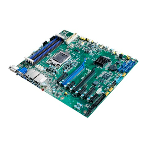
- Page 1 User Manual ASMB-786 LGA 1151 Intel® Xeon® E/8th Gen Intel® Core™ Series ATX Server Board with DDR4, 7 x PCIe, 6 x USB 3.1, 8 x SATAIII, Quad/Dual LANs, and IPMI...
- Page 2 No part of this manual may be reproduced, copied, translated, or transmitted in any form or by any means without the prior written permission of Advantech Co., Ltd. The information provided in this manual is intended to be accurate and reliable.
- Page 3 A Message to the Customer Advantech Customer Services Each Advantech product is built to the most precise specifications to ensure reliable performance in the harsh and demanding conditions typical of industrial environ- ments. Whether your new Advantech equipment is destined for the laboratory or the factory floor, you can be assured that your product will provide the reliability and ease of operation for which the name Advantech is renowned.
- Page 4 Caution! Batteries are at risk of exploding if incorrectly installed. Do not attempt to recharge, force open, or heat the battery. Replace the battery only with the same or equivalent type as recommended by the manufacturer. Dis- card used batteries according to the manufacturer's instructions. ASMB-786 User Manual...
- Page 5 Ordering Information Part Number Chipset Memory Display IPMI DVI, DDR4 288-pin ECC/non- ASMB-786G4-00A1 C246 HDMI, (AST-2400 ECC unbuffered DIMM onboard) DVI, DDR4 288-pin ECC/non- ASMB-786G2-00A1 C246 HDMI, ECC unbuffered DIMM ASMB-786 User Manual...
- Page 6 We have carefully inspected ASMB-786 mechanically and electrically before shipment. The product should be free of marks and scratches and in perfect working order upon receipt. When unpacking ASMB-786, check the prod- uct for signs of shipping damage (for example, damaged box, scratches, dents, etc.).
-
Page 7: Table Of Contents
1.5.2 Onboard LEDs (LED2, LED3, and LED4)........8 Table 1.4: Onboard LEDs (LED2, LED3, and LED4) ....8 ASMB-786 Block Diagram ................ 9 Figure 1.3 ASMB-786 Block Diagram.......... 9 Safety Precautions .................. 10 Jumper Settings ..................10 1.8.1 How to Set Jumpers..............10 Table 1.5: CMOS Clear (JCMOS1) ........... - Page 8 Figure 3.18UEFI Network Stack Configuration Screen ....73 3.3.16 CSM Configuration ..............74 Figure 3.19CSM Configuration Screen........74 Chipset....................79 Figure 3.20Chipset Configuration Screen ........79 3.4.1 System Agent (SA) Configuration..........79 Figure 3.21SA Configuration Screen.......... 79 ASMB-786 User Manual viii...
- Page 9 Table B.7: Power LED and Keyboard Lock (JFP3)....116 External Speaker Connector (JFP2) ............. 117 Table B.8: External Speaker Connector (JFP2)....... 117 HDD LED Connector (JFP2) ..............117 Table B.9: HDD LED Connector (JFP2) ........117 B.10 SNMP SMBus Connector (JFP2)............117 ASMB-786 User Manual...
- Page 10 Table B.21:Parallel Port (LPT1)..........121 B.22 System I/O Ports................... 122 Table B.22:System I/O Ports ............ 122 B.23 Interrupt Assignments ................122 Table B.23:Interrupt Assignments ..........122 B.24 First Motherboard Memory Map............123 Table B.24:First Motherboard Memory Map ......123 ASMB-786 User Manual...
-
Page 11: Chapter 1 Hardware Configuration
Chapter Hardware Configuration... -
Page 12: Introduction
786 provides up to four Gigabit Ethernet LAN via a dedicated PCIe bus with up to 500 MB/s bandwidth, thereby eliminating network bottlenecks. With the inclusion of an Intel® C246 chipset, ASMB-786 also supports eight onboard SATA III interfaces (bandwidth = 600 MB/s) with software RAID, six USB 3.1 ports, and seven USB 2.0 ports. -
Page 13: Specifications
COM cable connection), support only RS-232. PS/2 Keyboard and Mouse Connector: To save rear I/O space, ASMB-786 features a reserved 6-pin header onboard (KBMS1) that can be used to build two 6-pin mini-DIN connectors for easy connection to a PS/2 keyboard and mouse. -
Page 14: Graphics
Note! ASMB-786 features an onboard KBMS1 connector for external key- board/mouse usage. Please purchase an optional PS/2 keyboard/ mouse cable (P/N:1700019268-11) and bracket (P/N:1960063434N000) for installing on the rear slot of the chassis. 1.3.5 Graphics Graphics Processor: Integrated Intel® HD Graphics ... -
Page 15: Jumpers And Connectors
Jumpers and Connectors The ASMB-786 motherboard features connectors for integrating external devices, such as a hard disk drive or keyboard. Moreover, the board also has a number of jumpers that can be used to configure the system for specific applications. - Page 16 LAN1_USB1_2, LAN2_USB3_4 LAN2/USB 3.1 port 3, 4 stack connector LAN3_4 LAN3 & LAN4 connector (G4 SKU) LANLED1 LAN LED extension connector Low pin count connector for Advantech TPM LPC and LPC1 RS-232/422/485 modules LPT1 Parallel port PCIX1_SLOT1, PCIX1_SLOT3, PCIe x1 slot (Gen3 x1 link)
-
Page 17: Jumper And Connector Locations
GPIO1 SMBUS1 JFP3 EX_THR1 JWDT1 SYS_LED1 JTHR_SEL1 SYSFAN_SEL1 BAT2 LANLED1 JPEG1~2 JCMOS1 Figure 1.1 Jumper and Connector Locations COM1(reserved) VGA1 LAN4 LAN1 LAN2 USB2 USB4 USB1 USB3 DVI1 HDMI1 LAN3 AUDIO1 Figure 1.2 I/O Connectors (G4 SKU) ASMB-786 User Manual... -
Page 18: Onboard Lan Led Definition
Blinking green Green No Link 1.5.2 Onboard LEDs (LED2, LED3, and LED4) ASMB-786 features an onboard power LED indicator for 5 V Power, 5V Standby, and 3.3V AUX modes. Table 1.4: Onboard LEDs (LED2, LED3, and LED4) Description LED Definition... -
Page 19: Asmb-786 Block Diagram
6 x USB3.1 Connector SPI BIOS Pin Header HWM NCT7802Y LPC Connector PS/2 KB, MS CASE OPEN 2 x RS-232 Super I/O Nuvoton NCT6776D 8 bit GPIO Pin Header H/W Monitor LPT Connector Figure 1.3 ASMB-786 Block Diagram ASMB-786 User Manual... -
Page 20: Safety Precautions
1.8.1.1 CMOS Clear (JCMOS1) The ASMB-786 motherboard is equipped with a jumper that can erase CMOS data and reset the system BIOS information. This jumper is set with pins 1-2 closed as a default. To reset the CMOS data, set JCMOS1 to 2-3 closed for just a few seconds, and then move the jumper back to 1-2 closed. -
Page 21: Table 1.5: Cmos Clear (Jcmos1)
1.8.1.2 ME Update (JME1) ASMB-786 is equipped with a jumper that can update ME firmware. This jumper is set with pin 1-2 closed as a default. To update the ME firmware, set JME1 to 2-3 closed to disable ME for new ME firmware updates. -
Page 22: Sysfan_Sel1)
1.8.1.4 USB Power Switch (JUSB1/JUSB2) ASMB-786 is equipped with a jumper that supports a +5 VSB or +5 V power source for onboard USB ports. The JUSB1 jumper controls the USB 3.1 Gen2 ports of the rear window. The JUSB2 jumper controls the USB 2.0 and USB 3.1 Gen1 ports of the onboard header and connectors. -
Page 23: Table 1.10: Atx/At Mode Selector (Pson1)
1.8.1.6 ATX/AT Mode Selector (PSON1) ASMB-786 is equipped with a jumper that can support ATX or AT modes. This jumper is set with pin 2-3 closed as the default. To change to AT mode, set PSON to 1-2 closed. Table 1.10: ATX/AT Mode Selector (PSON1) -
Page 24: System Memory
System Memory The ASMB-786 motherboard features four 288-pin memory sockets for DDR4 unbuf- fered ECC/non-ECC 2666/2400/2133 MHz memory modules and supports a maxi- mum capacity of 64 GB (16 GB for each DIMM). Note! ASMB-786 does NOT support registered DIMMs (RDIMMs). -
Page 25: Chapter 2 Connecting Peripherals
Chapter Connecting Peripherals... -
Page 26: Introduction
LAN2_USB3_4, USB5~13) ASMB-786 provides up to 13 USB ports. USB7~13 are USB 2.0 ports that support data transmission rates of up to 480 Mbps, USB1~4 are USB 3.1 Gen2 ports with transmission rates of up to 10 Gbps, and USB5~6 are USB 3.1 Gen1 ports with transmission rates of up to 5 Gbps. -
Page 27: Usb Power Switch (Jusb1, Jusb2)
JUSB_1 JUSB_2 ASMB-786 allows users to switch the USB power between +5 VSB and +5 V. When the jumper is set as +5 V, the board does not support S3/S4. Refer to Section 1.8.1.4 “USB Power Switch” for information regarding the jumper settings. -
Page 28: Display Connector (Hdmi1_Vga1, Dvi1)
Display Connector (HDMI1_VGA1, DVI1) HDMI1_VGA1 DVI1 The ASMB-786 motherboard is equipped with VGA, DVI-D, and HDMI connectors to support triple display outputs. All display output ports can function simultaneously, however, the resulting performance may differ according to the OS. Additionally, one BMC VGA onboard connector (HDMI type) can support remote KVM displays with the inclusion of an optional VGA cable (P/N: 1700029038-01, for G4 SKU only). -
Page 29: Serial Ports (Com1 ~ Com2)
COM2 COM1 ASMB-786 features two serial ports onboard (one can be connected to the rear panel using the dedicated COM cable kit provided in the accessory box) for connecting a serial mouse, printer, or communications network. The IRQ and address ranges for these ports are fixed. -
Page 30: External Keyboard And Mouse (Kbms1)
External Keyboard and Mouse (KBMS1) KBMS1 The ASMB-786 motherboard is equipped with an onboard external keyboard and mouse connector, which offers system integrators greater flexibility when designing systems. Cables for the onboard KBMS connector and cable bracket installed at the rear of the system are available upon request (P/N: 1700019268-11, 1960063434N000). -
Page 31: Cpu Fan Connector (Cpufan0)
CPU Fan Connector (CPUFAN0) CPUFAN0 If a CPU fan is installed, this connector supports cooling fans that draw up to 2.5 A (30 W). ASMB-786 User Manual... -
Page 32: System Fan Connector (Sysfan0 ~ Sysfan3)
System FAN Connector (SYSFAN0 ~ SYSFAN3) SYSFAN3 SYSFAN0 SYSFAN2 SYSFAN1 If a system fan is installed, this connector supports cooling fans that draw up to 2.5 A (30 W). ASMB-786 User Manual... -
Page 33: Front Panel Connectors (Jfp1, 2, 3)
Front Panel Connectors (JFP1, 2, 3) Several external switches and LED indicators are provided for monitoring and con- trolling the ASMB-786 functions. JFP1 + JFP2 JFP3 PWRSW RESET JFP1 SNMP HDDLED HDDLED & & SM_BUS JPF2 SPEAKER PWRLED & KEYLOCK... -
Page 34: Power Led (Jfp3 Pins 1, 3)
External Speaker (JFP2 Pins 1, 4, 7, 10) The JFP2 connector pins 1, 4, 7, and 10 are for integrating an external speaker. ASMB-786 provides an onboard buzzer as an alternative. To enable the onboard buzzer, set pins 7-10 as closed. -
Page 35: Alarm Board Connector (Volt1)
The 8-pin VOLT1 connector should be connected to the alarm board on the Advan- tech chassis. This alarm board monitors the input voltage at +12 V, +5 V, +5 VSB, -5 V, +3.3 V and -12 V, and issues warning alerts if the power supply fails. ASMB-786 User Manual... -
Page 36: Case Open Connector (Jcase1)
JCASE1 to the chassis using an appropriate cable. Then change the BIOS settings to enable the case open function. If the chassis is opened, the BIOS will issue a warning message alerting of a chassis intrusion during system reboot and post screen. ASMB-786 User Manual... -
Page 37: Front Panel Lan Indicator Connector (Lanled1)
2.12 Front Panel Indicator Connector (LANLED1) LANLED1 is an extended connector for LAN1~LAN4. LAN_LED1 ASMB-786 User Manual... -
Page 38: Serial Ata Interface (Sata0 ~ 7)
SATA1 SATA4 SATA2 SATA5 SATA6 SATA7 ASMB-786 features eight high-performance serial ATA III interfaces (up to 600 MB/s) for massive storage applications. Software RAID 0, 1, 10, and can be supported with Intel® Rapid Storage Technology enterprise. ASMB-786 User Manual... -
Page 39: Pcie X16 Expansion Slots
PCIEX16_SLOT6 PCIEX16_SLOT4 ASMB-786 provides one PCIe x16 slot (x16 link) or two PCIe x16 slots (x8 link) for users to install additional VGA cards for applications that require increased graphics performance than that offered by the CPU embedded graphics controller, or that require high-bandwidth I/O cards, such as a frame grabber card, RAID card, or 10G LAN card. - Page 40 If an ASMB-RF348-21A1E riser card is installed and the PCIe x16 slot set to x8/x8 mode, the system can support one PCIe x4 (bottom slot) and one PCIe x8 (top slot). The middle PCIe x4 slot of the riser card is disabled by default. ASMB-786 User Manual...
-
Page 41: Pcie X4 Expansion Slots (Pciex4_Slot2, 7)
2.15 PCIe x4 Expansion Slots (PCIEx4_Slot2, 7) PCIEX4_SLOT7 PCIEX4_SLOT2 Both PCIEx4_Slot2 and PCIEx4_Slot7 feature Gen3 x4 link speed. Cards with higher speeds can be installed but will have to be downgraded for the x4 link. ASMB-786 User Manual... -
Page 42: Pcie X1 Expansion Slots (Pciex1_Slot1, 3, 5)
2.16 PCIe x1 Expansion Slots (PCIEx1_Slot1, 3, 5) PCIEX4_SLOT1 PCIEX4_SLOT3 PCIEX4_SLOT5 PCIEx4_Slot1, PCIEx4_Slot3, and PCIEx4_Slot5 feature Gen3 x1 link speed. Cards with higher speeds can be installed but will have to be downgraded for the x1 link. ASMB-786 User Manual... -
Page 43: Auxiliary Power Connector (Atx12V1)
(PSU) that complies with ATX 12V Specification 2.0 (or a later version). Remember to connect the 8-pin power plug, or 4-pin-to-8-pin convertor cable (P/N:1700019748) if no 8-pin power plug is installed on the PSU, otherwise the system will not boot. ATX12V1 ASMB-786 User Manual... -
Page 44: Spi Flash Connector (Spi_Cn1)
2.18 SPI Flash Connector (SPI_CN1) The SPI flash programmer pin header (for RMA) can be connected to the BIOS-flash- ing tools for flashing the BIOS. Remember to power off the ASMB-786 motherboard before flashing the BIOS. SPI_CN1 ASMB-786 User Manual... -
Page 45: Low-Pin-Count Connector (Lpc1)
2.19 Low-Pin-Count Connector (LPC1) LPC1 The LPC connector on the ASMB-786 motherboard is reserved for Advantech’s TPM and COM RS-232/422/485 modules. Part Number LPC Module PCA-TPM-00A1E TPM 1.2 module PCA-TPM-00B1E TPM 2.0 module PCA-COM232-00A1E 4-port RS-232 module connected to an LPC connector... -
Page 46: Parallel Port (Lpt1)
2.20 Parallel Port (LPT1) LPT1 Parallel ports are typically used to connect the motherboard to a printer. The ASMB- 786 motherboard includes an onboard parallel port that can be accessed through a 25-pin flat-cable connector. ASMB-786 User Manual... -
Page 47: Pmbus Connector (Pmbus1)
2.21 PMBUS Connector (PMBUS1) The PMBUS connector on ASMB-786 is reserved for communicating with the power supply via BMC (G4 SKU). PMBUS1 ASMB-786 User Manual... - Page 48 ASMB-786 User Manual...
-
Page 49: Bios Operation
Chapter BIOS Operation... -
Page 50: Introduction
The Setup program features a number of menus with multiple options for adjusting the configuration or enabling or disabling the special features. This chapter explains the basic navigation of the ASMB-786 BIOS Setup screens. Figure 3.1 Main BIOS Setup Screen The AMI BIOS ROM features a built-in Setup program that allows users to modify the basic system configuration. -
Page 51: Entering Bios Setup
System Date options using the <Arrow> keys. Enter new values via the keyboard. Press the <Tab> key or the <Arrow> keys to move between fields. The date must be entered in MM/DD/YY format. The time must be entered in HH:MM:SS format. ASMB-786 User Manual... -
Page 52: Advanced Bios Features
CPU configuration, to access the sub menu for that item. This section describes all Advanced BIOS Setup options and their sub menus, and provides images of the Advanced BIOS Setup screens for user reference. Figure 3.3 Advanced Tab of the BIOS Setup Screen ASMB-786 User Manual... -
Page 53: Platform Misc Configuration
BIOS control. The default setting is Disabled for BIOS control. Wake System From S5 This item allows users to Enable/Disable “System Wake On Alarm Event”. When Enabled, the system will wake if an alarm event is detected. ASMB-786 User Manual... -
Page 54: Cpu Configuration
Active Processor Cores This item allows users to set the number of cores Enabled for each processor package. Advanced Encryption Standard (AES) This item allows users to Enable/Disable the Advanced Encryption Standard instruction set. ASMB-786 User Manual... -
Page 55: Power And Performance
Boot Performance Mode This item allows users to select the performance state that the BIOS will set before OS handoff. Intel® SpeedStep™ This item allows users to Enable/Disable support for more than two frequency ranges. ASMB-786 User Manual... -
Page 56: Pch-Fw Configuration
This item allows users to Enable/Disable CPU power management. This func- tion instructs the CPU to go into a C state when not 100% utilized. 3.3.4 PCH-FW Configuration Figure 3.7 PCH-FW Configuration Screen This screen shows the Intel® Management Engine configuration settings. ASMB-786 User Manual... - Page 57 3.3.4.1 AMT Configuration ASF Support This item allows users to Enable/Disable Alert Standard Format (ASF) support. USB Provisioning of AMT This item allows users to Enable/Disable AMT USB provisioning. ASMB-786 User Manual...
- Page 58 Activate Remote Assistance Process This item allows users to Enable/Disable the trigger CIRA boot function. Net- work access must be activated first from the MEBx configuration menu. ASMB-786 User Manual...
- Page 59 PET events. WatchDog This item allows users to Enable or disable the watchDog timer. ASF Sensor Table This item allows users to add an ASF sensor table into an ASF ACPI table. ASMB-786 User Manual...
- Page 60 Secure Erase Configuration Secure Erase Mode This item allows users to set the Secure Erase Mode as “Simulated” or “Rear”. Force Secure Erase This item allows users to Enable/Disable Force Secure Erase on next bootup. ASMB-786 User Manual...
- Page 61 MEBx OEM Debug Menu Enable This item allows users to Enable/Disable the OEM debug menu in MEBx. Unconfigure ME This item allows users to Enable/Disable to unconfigure the ME by resetting the MEBx password to the default. ASMB-786 User Manual...
- Page 62 This item allows users to adjust the resolution for Non-UI text mode. UI Mode Resolution This item allows users to adjust the resolution for UI text mode. Graphics Mode Resolution This item allows users to adjust the resolution for Graphics mode. ASMB-786 User Manual...
- Page 63 3.3.4.6 Firmware Update Configuration ME FW Image Re-Flash This item allows users to Enable/Disable the ME FW Image Re-Flash function. ASMB-786 User Manual...
-
Page 64: Trusted Computing
3.3.5 Trusted Computing Figure 3.8 TPM Settings Screen Security Device Support This item allows users to Enable/Disable TPM support. Additionally, users can integrate an Advantech LPC TPM module to enable TPM function. ASMB-786 User Manual... -
Page 65: Acpi Settings
This item allows users to specify the ACPI sleep state when the system enters Suspend mode. Lock Legacy Resources This item allows users to Enable/Disable legacy resource locking. S3 Video Repost This item allows users to Enable/Disable S3 video reposting. ASMB-786 User Manual... -
Page 66: Smart Settings
3.3.7 SMART Settings Figure 3.10 SMART Settings Screen SMART Self-Test This item allows users to Enable/Disable SMART self-testing for all HDDs dur- ing POST. ASMB-786 User Manual... -
Page 67: Com1/2 Configuration
3.3.8 COM1/2 Configuration Figure 3.11 COM1/2 Configuration Screen COM1 Configuration Serial Port This item allows users to Enable/Disable serial port COM1. Change Settings This item allows users to optimize the super I/O device settings. ASMB-786 User Manual... - Page 68 COM2 Configuration Serial Port This item allows users to Enable/Disable serial port COM2. Change Settings This item allows users to optimize the super I/O device settings. ASMB-786 User Manual...
- Page 69 This item allows users to Enable/Disable the parallel port (LPT/LPTE). Change Settings This item allows users to optimize the super I/O device settings. Device Mode This item allows users to change the printer port mode. ASMB-786 User Manual...
-
Page 70: Nct6776 Hw Monitor
NCT6776 HW Monitor Figure 3.12 PC Health Status Screen CPU Warning Temperature This item allows users to set the CPU warning temperature threshold. When the system reaches the warning temperature, an alarm warning will be emitted. ASMB-786 User Manual... - Page 71 Enabled and the case is opened, a warning message will be displayed in the POST screen. Ensure that the board is paired with the chassis kit correctly to facilitate this function. WatchDog Timer This item allows users to Enable/Disable the watchdog timer. ASMB-786 User Manual...
- Page 72 1. Normal Mode - The system will adjust the fan speed automatically. 2. Quiet Mode - The fan will rotate at the lowest speed to minimize noise. 3. Disabled - Smart control of fans is Disabled and all fans run at full speed. ASMB-786 User Manual...
-
Page 73: Pca-Com232/Com485 Super I/O Configuration
This item is only available if a PCA COM module is installed. Figure 3.13 PCA-COM Configuration Screen ASMB-786 can support an extra four COM ports through the LPC connector. To implement this expansion, users must install a PCA-COM232-00A1E or PCA- COM485-00A1E I/O extension module in the LPC connector. - Page 74 Serial Port 1 Configuration Serial Port This item allows users to Enable/Disable Serial Port 1. Change Settings This item allows users to set the resource allocation for Serial Port 1. ASMB-786 User Manual...
-
Page 75: Serial Port Console Redirection
Change Settings This item allows users to set the resource allocation for Serial Port 4. 3.3.11 Serial Port Console Redirection Figure 3.14 Serial Port Console Redirection Screen Console Redirection This item allows users to Enable/Disable console redirection. ASMB-786 User Manual... - Page 76 Legacy Console Redirection Settings ASMB-786 User Manual...
- Page 77 OS and legacy OPROM messages. – Resolution This item allows users to set the number of rows and columns that support redirection on legacy OS. – Redirect After POST This item allows users to Enable/Disable redirection after POST. When ASMB-786 User Manual...
-
Page 78: Intel® Trusted Execution Technology (Txt) Information
“Bootloader” is selected, legacy console redirection is Disabled before boot- ing to legacy OS. When “Always Enable” is selected, legacy console redirec- tion is Enabled for legacy OS. 3.3.12 Intel® Trusted Execution Technology (TXT) Information Figure 3.15 Intel® TXT Information Screen ASMB-786 User Manual... -
Page 79: Pci Subsystem Settings
This item allows users to Enable/Disable hot-plugging slot functionality. When this item is Enabled, a setup screen is displayed for selecting the PCI resource padding for hot-plugging. Note! Altering the PCI device settings may cause unwanted side effects. Specifically, the system may hang. ASMB-786 User Manual... -
Page 80: Usb Configuration
This item allows users to configure the mass storage device emulation type. The Auto emulates devices according to their media format. Optical drives are emu- lated as CDROM and drives with no media are emulated according to the drive type. ASMB-786 User Manual... - Page 81 ASMB-786 User Manual...
- Page 82 ASMB-786 User Manual...
-
Page 83: Uefi Network Stack Configuration
UEFI Network Stack Configuration Figure 3.18 UEFI Network Stack Configuration Screen UEFI Network Stack This item allows users to Enable/Disable the UEFI network stack. IPv4/IPv6 PXE Support This item allows users to Enable/Disable IPv4/IPv6 PXE boot support. ASMB-786 User Manual... -
Page 84: Csm Configuration
This item allows users to specify the wait time in seconds for pressing the <ESC> key to abort PXE bootup. Media Detect Count This item allows users to specify the number of times the system will search for media. 3.3.16 CSM Configuration Figure 3.19 CSM Configuration Screen ASMB-786 User Manual... - Page 85 This item allows users to configure the GA20 settings when RT code is exe- cuted above 1 MB. When set as “Upon Request”, GA20 can be disabled via the BIOS. When set as “Always”, GA20 disabling is not allowed. ASMB-786 User Manual...
- Page 86 Option ROM execution. When set as “Immediate”, the trap is executed right away. When set as “Postponed”, the trap is executed during legacy boot. Boot Option Filter This item allows users to set the priority for legacy/UEFI ROMs. ASMB-786 User Manual...
- Page 87 Option ROM Execution Network This item allows users to control the execution of UEFI and the legacy PXE Option ROM. Storage This item allows users to control the execution of UEFI and the legacy storage Option ROM. ASMB-786 User Manual...
- Page 88 This item allows users to control the execution of UEFI and the legacy video Option ROM. Other PCI Devices This item allows users to control the execution of the Option ROM policy for devices other than network, storage, or video. ASMB-786 User Manual...
-
Page 89: Chipset
Chipset Figure 3.20 Chipset Configuration Screen 3.4.1 System Agent (SA) Configuration Figure 3.21 SA Configuration Screen ASMB-786 User Manual... - Page 90 Memory Configuration Max TOLUD This item allows users to set the maximum TOLUD value. When the Dynamic assignment option is elected, TOLUD is automatically adjusted according to the largest MMIO length of the installed add-on cards. ASMB-786 User Manual...
- Page 91 3.4.1.2 Graphics Configuration Primary Display This item allows users to configure the primary display settings. Options include Auto, IGFX, PEG, and PCI Graphics. ASMB-786 User Manual...
- Page 92 VGA (with cable) > onboard VGA. For G4 SKU, BMC VGA can be set as primary by changing the “Auto” default setting to “PCI”. Internal Graphics This item allows users keep IGFX enabled based on the setup options. 3.4.1.3 PEG Port Configuration ASMB-786 User Manual...
- Page 93 PCIe SLOT6 (ROOT PORT2) This item allows users to Enable/Disable Root Port2 and configure the PEG 0:1:2 max. link speed. PEG Port Feature Configuration This item allows users to Enable/Disable the detection of non-compliant PCI Express devices in PEG. ASMB-786 User Manual...
-
Page 94: Pch-Io Configuration
This item allows users to Enable/Disable “PCIE Wake From S5” functionality. PowerOn by Modem This item allows users to Enable/Disable “PowerOn by Modem” functionality. Deep Sleep This item allows users to Enable/Disable Deep Sleep support. ASMB-786 User Manual... - Page 95 We recommend users wait for more than 30 seconds to power the system back on after a power failure. However, the system will automatically power back on if the power sup- ply is restored within 30 seconds, before the 5VSB drops, even when configured as Power Off. ASMB-786 User Manual...
-
Page 96: Figure 3.23Pci Express Configuration Screen
Figure 3.23 PCI Express Configuration Screen PCIe Slot 1/2/3/5/7 This item allows users to control the PCI Express root port. PCIe Speed This item allows users to set the PCIe speed for PCIe slots 1, 2, 3, 5, and 7. ASMB-786 User Manual... -
Page 97: Figure 3.24Sata And Rst Configuration Screen
If this item is configured as Disabled, all drives will spinup at boot. SATA Device Type This item allows users to determine whether the SATA port is connected to a SSD or HDD. ASMB-786 User Manual... -
Page 98: Figure 3.25Usb Configuration Screen
3.4.2.3 USB Configuration Figure 3.25 USB Configuration Screen XHCI Disable Compliance Mode This item allows users to Enable/Disable compliance mode. The default setting is Disabled. However, for compliance mode testing, this item must be Enabled. ASMB-786 User Manual... -
Page 99: Figure 3.26Security Configuration Screen
Enabled to ensure flash protection in SMM. Force Unlock on All GPIO Pads This item allows users to Enable/Disable forced unlocking of all GPIO pads. When Enabled, the BIOS will force all GPIO pads to the unlocked state. ASMB-786 User Manual... -
Page 100: Figure 3.27Hd Audio Configuration Screen
3.4.2.5 HD Audio Configuration Figure 3.27 HD Audio Configuration Screen HD Audio This item allows users to control the detection of HD audio devices. ASMB-786 User Manual... -
Page 101: Security
Select the Security tab from the main BIOS Setup menu. All Security menu items, such as password protection, are described in this section. To access the sub menu of any item, navigate to the item using the <Arrow> keys and press <Enter>. ASMB-786 User Manual... -
Page 102: Boot
Boot Option Priorities This item allows users to set the boot priority for devices. Note! UEFI devices can be recognized as a default. Enable device recognition in the CSM Configuration settings to support legacy devices when needed. ASMB-786 User Manual... -
Page 103: Save And Exit
This item allows users to discard all changes to the system configuration. Restore Defaults This item allows users to restore all BIOS configuration settings to the original defaults. Save as User Defaults This item allows users to save all configuration settings as a user default. ASMB-786 User Manual... -
Page 104: Server Management
The BMC is initialized at the same time as the BIOS when the system is powered on. The host-to-BMC interface takes approximately 30 seconds to initialize. The system will emit a beep sound but no display will be output to the monitor until the interface initialization is complete. ASMB-786 User Manual... - Page 105 Note! This item is only available for the G4 SKU with onboard IPMI. BMC Counter This item allows users to set the BMC counter value as either 6, 8, 10, or 12. ASMB-786 User Manual...
-
Page 106: System Event Log
3.8.1 System Event Log ASMB-786 User Manual... - Page 107 This item allows users to specify the system actions in response to a full SEL. Log EFI Status Codes This item allows users to Enable/Disable logging of EFI status codes or to log only error codes or progress codes. ASMB-786 User Manual...
-
Page 108: Bmc Self-Test Log
BMC Self-Test Log Erase Log This item allows users to Enable/Disable log erasing upon system reset. When Log is Full This item allows users to specify the system actions in response to a full log. ASMB-786 User Manual... -
Page 109: Bmc Network Configuration
(by BIOS or BMC). If set as Unspecified, the BMC network parameters will not be modified during BIOS phase. For the ASMB-786 motherboard, the LAN2 port is reserved for IPMI to share a NIC. ASMB-786 User Manual... - Page 110 ASMB-786 User Manual...
-
Page 111: Chapter 4 Driver Installation
Chapter Driver Installation... -
Page 112: Before Installation
Before Installation To ensure all ASMB-786 drivers are up-to-date, the drivers are available online for download from the Advantech support website at https://advt.ch/searc8f16d. Most display drivers must have the relevant software application already installed in the system before the enhanced display drivers can be installed. Additionally, many of the installation procedures assume that users are familiar with both the relevant software applications and OS commands. -
Page 113: Graphics
4.2.3 ASMB-786 is equipped with up to four Gigabit Ethernet LANs via dedicated PCI Express x1 lanes (GbE LAN1: Intel® I219LM; GbE LAN2~4: Intel® I210-AT) that offer bandwidths of up to 500 MB/sec to eliminate network bottlenecks while incorpo- rating Gigabit Ethernet at 1000 Mbps. -
Page 114: Sata Raid
RAID 10 arrays use four hard drives to create a combination of RAID levels 0 and 1. The data is striped across a two-drive array forming the RAID 0 component. Each of the drives in the RAID 0 array is then mirrored by a RAID 1 component. ASMB-786 User Manual... -
Page 115: Appendix A Watchdog Timer
Appendix Watchdog Timer... -
Page 116: Watchdog Timer Overview
The ASMB-786 watchdog timer can be used to monitor system software operations and implement corrective actions if the software fails to function within the pro- grammed period. This chapter describes the operation of the watchdog timer and provides programming instructions. - Page 117 Unlock NCT6776 Select the watchdog timer register Enable the watchdog timer function Use the watchdog timer Lock NCT6776 ASMB-786 User Manual...
-
Page 118: Example Programs
Out dx,al Out dx,al ;----------------------------------------------------------- Mov al,07h ; Select registers of watchdog timer Out dx,al Inc dx in al,dx Or al,08h Out dx,al ;----------------------------------------------------------- Dec dx; Enable the function of watchdog timer Mov al,30h Out dx,al Inc dx ASMB-786 User Manual... - Page 119 Or al,08h Out dx,al ;----------------------------------------------------------- Dec dx ; Enable the function of watchdog timer Mov al,30h Out dx,al Inc dx Mov al,01h Out dx,al ;----------------------------------------------------------- Dec dx ; Set minute as counting unit Mov al,0f5h Out dx, al ASMB-786 User Manual...
- Page 120 Inc dx In al,dx Or al,01h Out dx,al ;----------------------------------------------------------- Dec dx ; Enable watchdog timer to be reset by mouse Mov al,0f7h Out dx,al Inc dx In al,dx Or al,80h Out dx,al ;----------------------------------------------------------- Dec dx ; lock NCT6776 ASMB-786 User Manual...
- Page 121 Out dx,al Generate a time-out signal without timer counting ;----------------------------------------------------------- Mov dx,2eh ; unlock NCT6776 Mov al,87h Out dx,al Out dx,al ;----------------------------------------------------------- Mov al,07h ; Select registers of watchdog timer Out dx,al Inc dx Mov al,08h Out dx,al ASMB-786 User Manual...
- Page 122 Dec dx ; Generate a time-out signal Mov al,0f7h Out dx,al ;Write 1 to bit 5 of F7 register Inc dx In al,dx Or al,20h Out dx,al ;----------------------------------------------------------- Dec dx ; lock NCT6776 Mov al,0aah Out dx,al ASMB-786 User Manual...
-
Page 123: Appendix B I/O Pin Assignments
Appendix I/O Pin Assignments... -
Page 124: Usb 2.0 Header (Usb7 ~ 12)
Table B.1: USB 2.0 Header (USB7 ~ 12) Signal Signal +5V_USB +5V_USB USB2_D1- USB2_D2- USB2_D1+ USB2_D2+ USB 3.1 Header (USB5_6) Table B.2: USB 3.1 Header (USB5_6) Signal Signal +5V_USB USB3_RX_D1- +5V_USB USB3_RX_D1+ USB3_RX_D2- USB3_RX_D2+ USB3_TX_D1- USB3_TX_D1+ USB3_TX_D2- USB3_TX_D2+ USB2_D1- USB2_D1+ USB2_D2- USB_OC USB2_D2+ ASMB-786 User Manual... -
Page 125: Vga Connector (Vga1)
VGA Connector (VGA1) Table B.3: VGA Connector (VGA1) Signal Signal Green Blue H-SYNC V-SYNC RS-232 Interface (COM1 ~ 2) Table B.4: RS-232 Interface (COM1 ~ 2) COM1/COM2 Signal ASMB-786 User Manual... -
Page 126: External Keyboard/Mouse Connector (Kbms1)
Table B.6: System Fan Power Connector (SYSFAN0 ~ 3) Signal +12 V Detect Power LED and Keyboard Lock (JFP3) Table B.7: Power LED and Keyboard Lock (JFP3) Signal LED power + (3.3 V) LED power - #keylock Ground ASMB-786 User Manual... -
Page 127: External Speaker Connector (Jfp2)
Table B.8: External Speaker Connector (JFP2) Signal SPK_VCC (+) SPK_OBS SPK_BUZ SPK_OUT (-) HDD LED Connector (JFP2) Table B.9: HDD LED Connector (JFP2) Signal HDD_LED+ HDD_LED- B.10 SNMP SMBus Connector (JFP2) Table B.10: SNMP SMBus Connector (JFP2) Signal HWM_SDA HWM_SCL ASMB-786 User Manual... -
Page 128: Atx Soft Power Switch (Jfp1)
Signal PWR-BTN B.12 Reset Connector (JFP1) Table B.12: Reset Connector (JFP1) Signal RST-BTN B.13 Front Panel Audio Connector (FPAUD1) Table B.13: Front Panel Audio Connector (FPAUD1) Signal Signal MIC2_L AGND MIC2_R PRESENSE LINE2_R MIC2_JD FRONT-IO_JD LINE2_L LINE2_JD ASMB-786 User Manual... -
Page 129: 8-Pin Alarm Board Connector (Volt1)
+12V B.15 Case Open Connector (JCASE1) Table B.15: Case Open Connector (JCASE1) Signal CASEOP B.16 Front Panel LAN LED Connector (LAN_LED1) Table B.16: LAN LED Connector (LANLED1) Signal Signal LAN1_LED_ACT# LAN2_LED_ACT# VCC3 VCC3 LAN3_LED_ACT# LAN4_LED_ACT# VCC3 VCC3 ASMB-786 User Manual... -
Page 130: Spi Flash Card Pin Connector (Spi_Cn1)
+3VSB SPI_CS# SPI_CLK SPI_MISO SPI_MOSI B.18 GPIO Connector (GPIO1) Table B.18: GPIO Connector (GPIO1) Signal Signal SIO_GPIO0 SIO_GPIO4 SIO_GPIO1 SIO_GPIO5 SIO_GPIO2 SIO_GPIO6 SIO_GPIO3 SIO_GPIO7 VCC_GPIO0 B.19 SMBUS Connector (SMBUS1) Table B.19: SMBUS Connector (SMBUS1) Signal Clock Data ASMB-786 User Manual... -
Page 131: Pmbus Connector (Pmbus1)
B.20 PMBUS Connector (PMBUS1) Table B.20: PMBUS Connector (PMBUS1) Signal SMB_SCL_PM SMB_SDA_PM SMB_ALT_PM +3.3V B.21 Parallel Port (LPT1) Table B.21: Parallel Port (LPT1) Signal Signal STROBE* GND* AFD* IGND ERR* INIT* ACK* SLIN* BUSY SLCT ASMB-786 User Manual... -
Page 132: System I/O Ports
Intel 8 series/C226 chipset family SMBus controller IRQ11 Available IRQ12 PS/2 mouse IRQ13 Numeric data processor IRQ14 Available IRQ15 Available IRQ3 Serial communication port 2 IRQ4 Serial communication port 1 IRQ5 Available IRQ6 Available IRQ7 Parallel port 1 (print port) ASMB-786 User Manual... -
Page 133: First Motherboard Memory Map
First Motherboard Memory Map Table B.24: First Motherboard Memory Map Address Range (Hex) Device E0000h - FFFFFh BIOS D0000h - DFFFFh Unused C0000h - CFFFFh VGA BIOS A0000h - BFFFFh Video memory 00000h - 9FFFFh Base memory ASMB-786 User Manual... - Page 134 ASMB-786 User Manual...
- Page 135 ASMB-786 User Manual...
- Page 136 No part of this publication may be reproduced in any form or by any means, such as electronically, by photocopying, recording, or otherwise, without prior written permission from the publisher. All brand and product names are trademarks or registered trademarks of their respective companies. © Advantech Co., Ltd. 2018...
Need help?
Do you have a question about the ASMB-786 and is the answer not in the manual?
Questions and answers