
Related Manuals for Advantech ASMB-785


Summary of Contents for Advantech ASMB-785
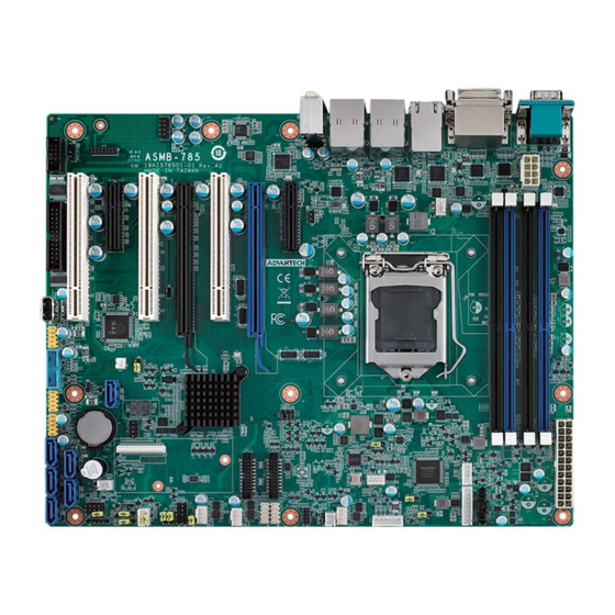
- Page 1 User Manual ASMB-785 LGA 1151 Intel® Xeon® E3-1200 v5/ v6 & 6th/7th Generation Core™ Series ATX Server Board with DDR4, 4 PCIe, 3 PCI, 6 USB 3.0, 6 COM, 6 SATA3, Quad/Dual LANs...
- Page 2 No part of this manual may be reproduced, copied, translated or transmitted in any form or by any means without the prior written permission of Advantech Co., Ltd. Information provided in this manual is intended to be accurate and reliable. How- ever, Advantech Co., Ltd.
- Page 3 Whether your new Advantech equipment is destined for the labo- ratory or the factory floor, you can be assured that your product will provide the reliability and ease of operation for which the name Advantech has come to be known.
-
Page 4: Declaration Of Conformity
Caution! There is a danger of a new battery exploding if it is incorrectly installed. Do not attempt to recharge, force open, or heat the battery. Replace the battery only with the same or equivalent type recommended by the man- ufacturer. Discard used batteries according to the manufacturer's instructions. ASMB-785 User Manual... - Page 5 Cooler / Heatsink LGA 1151 CPU cooler Support up to 91W 1960052651N021 CoolJag for 2U/4U chassis processor Riser AIMB-RF10F AIMB-RF10F-01A1E Advantech 1*PCIe x16 slot Card (1U riser card) AIMB-R430P (2U riser AIMB-R430P-03A2E Advantech 3*PCI slot card) ASMB-785 User Manual...
- Page 6 1 Warranty card If any of these items are missing or damaged, contact your distributor or sales repre- sentative immediately. We have carefully inspected the ASMB-785 mechanically and electrically before shipment. It should be free of marks and scratches and in perfect...
- Page 7 As you unpack the ASMB-785, check it for signs of ship- ping damage. (For example, damaged box, scratches, dents, etc.) If it is damaged or it fails to meet the specifications, notify our service department or your local sales representative immediately.
- Page 8 ASMB-785 User Manual viii...
-
Page 9: Table Of Contents
1.5.2 Onboard LEDs (LED2, LED3, LED4)..........7 Table 1.4: Onboard LED (LED2, LED3, LED4) ......7 ASMB-785 Block Diagram ................ 8 Figure 1.3 ASMB-785 Block Diagram.......... 8 Safety Precautions ..................9 Jumper Settings ..................9 1.8.1 How to set jumpers ............... 9 Table 1.5: JCMOS1 .............. - Page 10 Auxiliary 8-pin power connector (ATX12V1) ........... 32 2.18 SPI Flash Connector(SPI_CN1) ............. 33 2.19 Low Pin Count Connector (LPC1)............33 Table 2.6: Advantech LPC Module List ........33 2.20 Parallel Port (LPT1) ................34 2.21 PCI Clock Selection (JPCICLK1) ............34 Table 2.7: PCI Clock Selection (JPCICLK1) ......
- Page 11 Features ....................86 Installation ....................86 Windows OS Driver Setup (LAN) ............86 Chapter Intel ME ..........87 Introduction ..................... 88 Installation ....................88 Chapter Intel USB 3.0........89 Introduction ..................... 90 Installation ....................90 Chapter SATA RAID Setup ......91 ASMB-785 User Manual...
- Page 12 Table B.18:LAN LED Connector (LANLED1) ......110 Table B.19:LAN LED Connector (LANLED2) ......110 B.18 SPI_CN1: SPI Flash Card Pin Connector..........110 Table B.20:SPI_CN1:SPI Flash Card Pin Connector ....110 B.19 GPIO Connector (GPIO1) ..............111 Table B.21:GPIO Connector (GPIO1) ........111 ASMB-785 User Manual...
- Page 13 Table B.23:System I/O ports............. 111 B.22 Interrupt Assignments ................112 Table B.24:Interrupt assignments ..........112 B.23 1st MB Memory Map ................112 Table B.25:1st MB memory map ..........112 B.24 Parallel Port (LPT1)................113 Table B.26:Parallel Port (LPT1) ..........113 xiii ASMB-785 User Manual...
- Page 14 ASMB-785 User Manual...
-
Page 15: Chapter 1 Hardware Configuration
Chapter Hardware Configuration... -
Page 16: Introduction
PCIe x16 slots with x8 link from CPU, and two PCIe x4 slots from PCH. In addition, ASMB-785 also comes with three PCI slots via a discrete PCIe to PCI bridge chip to support legacy PCI expansion cards and has four or two Gigabit Ethernet LAN via dedicated PCIe bus, which offers bandwidth up to 300 MB/s. -
Page 17: Specifications
LPC: One LPC connector supports Advantech TPM LPC modules and COM 232/485 modules. (Slot-2 & 3 can't be used when COM module is installed.) GPIO: ASMB-785 supports 8-bit GPIO from super I/O for general purpose con- trol application. 1.3.5 Graphics ... -
Page 18: Ethernet Lan
Board weight: 0.75 kg (1.68 lb) Jumpers and Connectors Connectors on the ASMB-785 motherboard link it to external devices such as hard disk drives and a keyboard. In addition, the board has a number of jumpers that are used to configure your system for your application. -
Page 19: Table 1.2: Connector List
SM Bus From PCH GPIO1 8-bit GPIO header FPAUD1 Audio front panel header COM2, COM3_4, COM5_6 Serial port: RS-232 Low pin count connector for Advantech TPM LPC and LPC1 RS232/422/485 modules. VOLT1 Voltage display AUDIO1 Audio connector For optional battery kit... -
Page 20: Board Layout: Jumper And Connector Locations
FAN1 & 2 JUSB2 THR1 KBMS1 COM5_6 Figure 1.1 Jumper and Connector Locations COM1 DVI1 LAN1 LAN2 DVI2 USB1_2 USB5_6 AUDIO1 ASMB-785G2-00A1E COM1 LAN1 DVI1 LAN3 LAN2 VGA1 DVI2 LAN4 USB1_2 USB5_6 AUDIO1 ASMB-785G4-00A1E Figure 1.2 I/O connectors ASMB-785 User Manual... -
Page 21: Onboard Lan Led Definition
Active Green Blinking green No Link 1.5.2 Onboard LEDs (LED2, LED3, LED4) The ASMB-785 has onboard power LED for 5V Power, 5V Standby and 3.3V AUX. Table 1.4: Onboard LED (LED2, LED3, LED4) Description LED Definition Off: On (Green): 5V_LED2... -
Page 22: Asmb-785 Block Diagram
LPC to UART LPC BUS 4 x RS-232 F81216AD LPC Connector LPC BUS PS/2 KB, MS Header Super I/O SPI BIOS Nuvoton NCT6776D 2 x RS-232 128M-bit 8 bit GPIO Pin Header LPT Connector Figure 1.3 ASMB-785 Block Diagram ASMB-785 User Manual... -
Page 23: Safety Precautions
1.8.1.1 CMOS and ME clear (JCMOS1) The ASMB-785 motherboard contains a jumper that can erase CMOS data and reset the system BIOS information. Normally this jumper should be set with pins 1-2 closed. If you want to reset the CMOS data, set JCMOS1 to 2-3 closed for just a few seconds, and then move the jumper back to 1-2 closed. -
Page 24: Table 1.5: Jcmos1
The ASMB-785 contains a watchdog timer that will reset the CPU. This feature means the ASMB-785 will recover from a software failure or an EMI problem. The JWDT1 jumper settings control the outcome of what the computer will do in the event the watchdog timer is tripped. -
Page 25: Table 1.8: Usb Power Switch (Jusb1/Jusb2)
1.8.1.4 USB power switch (JUSB1/JUSB2) The ASMB-785 contains a jumper that can support on board USB ports power source from +5Vsb or +5V. The JUSB1 jumper controls the USB2.0 and 3.0 ports of rear window. The JUSB2 jumper controls the USB2.0 and 3.0 ports of onboard header and connectors. -
Page 26: Table 1.10: Atx/At Mode Selector (Pson1)
1.8.1.6 ATX/AT mode selector (PSON1) The ASMB-785 contains a jumper that can support ATX or AT mode. Normally this jumper should be set with pin 2-3 closed. If you want to change to AT mode, set PSON to 1-2 closed. -
Page 27: System Memory
*PCI Clock at 33 MHz 2-3 closed * default setting System Memory ASMB-785 has four 288-pin memory sockets for DDR4 unbuffered ECC/Non-ECC 1600/1866/2133/2400 MHz memory modules with maximum capacity of 64 GB (Max- imum 16 GB for each DIMM). Note! ASMB-785 does NOT support registered DIMMs (RDIMMs). -
Page 28: Pci Bus Routing Table
1.11 PCI Bus Routing Table PCI_SLOT1 PCI_SLOT3 PCI_SLOT5 PCI slot INT AD16 AD17 AD18 ASMB-785 User Manual... -
Page 29: Chapter 2 Connecting Peripherals
Chapter Connecting Peripherals... -
Page 30: Introduction
USB Ports (LAN1_USB1_2, LAN2_USB5_6, USB3_4, USB7~13) ASMB-785 provides up to 13 USB ports. USB7~13 are USB 2.0 ports supporting transmission rates up to 480 Mbps, and USB1~6 are USB 3.0 ports supporting trans- mission rates up to 5Gbps.These ports support Plug & Play and hot swapping for up to 127 external devices, which are able to be disabled in the BIOS menu. -
Page 31: Usb Power Switch (Jusb1/Jusb2)
USB Power Switch (JUSB1/JUSB2) JUSB2 JUSB1 ASMB-785 allows user to set USB power between +5VSB and +5V. When the jumper is set as +5V, the board doesn't support S3/S4. Jumper USB Ports JUSB1 Rear Window: USB1_2, USB3_4, USB5_6 JUSB2 On board: USB7_8, USB9_10, USB11_12, USB13... -
Page 32: Vga And Dvi1, Dvi2 Connector
VGA and DVI1, DVI2 Connector DVI1_DVI2 VGA_COM1 The ASMB-785 includes one VGA and two DVI-D connectors, users could display all ports at the same time (The result may different because of OS support limitations). ASMB-785 User Manual... -
Page 33: Serial Ports (Com1 ~ Com6)
COM2 COM5_6 COM3_4 The ASMB-785 offers six serial ports (one on the rear panel and five onboard). All ports can connect to a serial mouse, printer or communications network. The IRQ and address ranges for those ports are fixed. However, if you want to dis- able the port or change these parameters later, you can do this in the system BIOS setup. -
Page 34: External Keyboard & Mouse (Kbms1)
External Keyboard & Mouse (KBMS1) KBMS1 There is an onboard external keyboard and mouse connector on the motherboard. That gives system integrators greater flexibility in designing their systems. ASMB-785 User Manual... -
Page 35: Cpu Fan Connector (Cpufan0)
CPU Fan Connector (CPUFAN0) CPUFAN0 If a fan is used, this connector supports cooling fans that draw up to 2.5 A (30 W). ASMB-785 User Manual... -
Page 36: System Fan Connector (Sysfan0 ~ Sysfan3)
System FAN Connector (SYSFAN0 ~ SYSFAN3) SYSFAN3 SYSFAN2 SYSFAN1 SYSFAN0 If a fan is used, this connector supports cooling fans that draw up to 2.5 A (30 W). ASMB-785 User Manual... -
Page 37: Front Panel Connectors (Jfp1/2/3)
Front Panel Connectors (JFP1/2/3) There are several external switches and LEDs to monitor and control the ASMB-785. JFP1+JFP2 JFP3 JFP1 PWRSW RESET & & SNMP HDDLED HDDLED SM_BUS JPF2 SPEAKER JFP3 PWRLED & KEYLOCK ASMB-785 User Manual... -
Page 38: Power Led (Jfp3 Pins 1, 3)
2 3 4 2.9.2 External Speaker (JFP2 pins 1, 4, 7, 10) JFP2 pins 1, 4, 7, 10 connector for an external speaker. The ASMB-785 provides an onboard buzzer as an alternative. To enable the onboard buzzer, set pins 7-10 as closed. -
Page 39: Reset Connector (Jfp1 Pins 9 & 12)
2.10 8-pin Alarm Board Connector (VOLT1) VOLT1 VOLT1 connects to the alarm board of Advantech chassis. These alarm boards monitors the input voltage of +12V, +5V, +5Vsb, -5V +3.3V and -12V, and give warn- ings if a power supply fails. -
Page 40: Case Open Connector (Jcase1)
Please refer to Chapter 3 BIOS Operation, section 3.2.2.6 HW Monitor. If the chassis is opened, the BIOS will inform you with a warning message of a chassis intrusion during system reboot and post screen. ASMB-785 User Manual... -
Page 41: Front Panel Lan Indicator Connector (Lanled1, Lanled2)
Table 2.3: Front Panel LAN Indicator Connector (LANLED1) Signal Signal LAN1_LED0_ACT LAN2_LED1_ACT VCC3_LAN1LED VCC3_LAN2LED LAN1_LED1_1000M LAN2_LED2_1000M LAN1_LED2_100M LAN2_LED0_100M VCC3 Table 2.4: Front Panel LAN Indicator Connector (LANLED2) Signal Signal LAN3_LED1_ACT LAN4_LED1_ACT VCC3_LAN3LED VCC3_LAN4LED LAN3_LED2_1000M LAN4_LED2_1000M LAN3_LED0_100M LAN4_LED0_100M VCC3 LANLED2 LANLED1 ASMB-785 User Manual... -
Page 42: Serial Ata Interface (Sata0~5)
2.13 Serial ATA Interface (SATA0~5) SATA0 SATA1 SATA2 SATA3 SATA5 SATA4 ASMB-785 features six high performance serial ATA III interfaces (up to 600 MB/s, blue connector). ASMB-785 User Manual... -
Page 43: Pci Slots (Pci_Slot1, Pci_Slot3, Pci_Slot5)
2.14 PCI Slots (PCI_SLOT1, PCI_SLOT3, PCI_SLOT5) PCI_SLOT1 PCI_SLOT3 PCI_SLOT5 There are three 32bit PCI slots designed on ASMB-785, and default clock is 33 Mhz. PCI clock could be selected between 33 or 66 MHz by JPCICLK1 jumper. ASMB-785 User Manual... -
Page 44: Pcie X16 Expansion Slot (Pciex16_Slot4 And Pciex16_Slot6)
PCIEX16_ SLOT6 The ASMB-785 provides one PCIe x16 slots (x16 link) or two PCIe x16 slots (x8 link) for users to install add-on VGA cards when their applications require higher graphics performance than the CPU embedded graphics controller can provide, or high band- width demanded I/O cards, such as a frame grabber card, RAID card and a 10G LAN card. -
Page 45: Pcie X4 Expansion Slot (Pciex4_Slot2, Pciex4_Slot7)
2.16 PCIe x4 Expansion Slot (PCIEX4_SLOT2, PCIEX4_SLOT7) PCIEX4_SLOT2 PCIEX4_SLOT7 PCIEX4_SLOT2 is Gen3 x4 link. PCIEX4_SLOT7 is Gen3 x4 link. ASMB-785 User Manual... -
Page 46: Auxiliary 8-Pin Power Connector (Atx12V1)
For a fully configured system, we recommend that you use a power supply unit (PSU) that complies with ATX 12V Specification 2.0 (or later version). Do not forget to con- nect the 8-pin EATX12V power plug, otherwise the system will not boot. ATX12V1 ASMB-785 User Manual... -
Page 47: Spi Flash Connector(Spi_Cn1)
Low Pin Count Connector (LPC1) LPC1 LPC connector on ASMB-785 is reserved for Advantech TPM and COM 232/485 modules. The slot-2 & 3 can't be used when Advantech’s COM module is installed. Table 2.6: Advantech LPC Module List Advantech P/N... -
Page 48: Parallel Port (Lpt1)
4 ports RS-485 module connect to LPC connector 2.20 Parallel Port (LPT1) LPT1 The parallel port is normally used to connect the motherboard to a printer. The ASMB-785 includes an onboard parallel port, accessed through a 25-pin flat-cable connector, LPT1. 2.21 PCI Clock Selection (JPCICLK1) JPCICLK1 JPCICLK1 is a jumper to select a PCI slot clock speed between 66 or 33 MHz, the default setting is 33 MHz (2-3 closed). -
Page 49: Table 2.7: Pci Clock Selection (Jpciclk1)
Table 2.7: PCI Clock Selection (JPCICLK1) Function Jumper Setting PCI Clock at 66 MHz 1-2 closed *PCI Clock at 33 MHz 2-3 closed * default setting ASMB-785 User Manual... - Page 50 ASMB-785 User Manual...
-
Page 51: Bios Operation
Chapter BIOS Operation... -
Page 52: Introduction
The Setup program uses a number of menus for making changes and turning the special features on or off. This chapter describes the basic navigation of the ASMB-785 setup screens. Figure 3.1 Main setup screen AMI’s BIOS ROM has a built-in Setup program that allows users to modify the basic... -
Page 53: Entering Bios Setup
System Date using the <Arrow> keys. Enter new values through the keyboard. Press the <Tab> key or the <Arrow> keys to move between fields. The date must be entered in MM/DD/YY format. The time must be entered in HH:MM:SS format. ASMB-785 User Manual... -
Page 54: Advanced Bios Features Setup
3.2.2 Advanced BIOS Features Setup Select the Advanced tab from the ASMB-785 setup screen to enter the Advanced BIOS setup screen. You can select any of the items in the left frame of the screen, such as CPU configuration, to go to the sub menu for that item. You can display an Advanced BIOS Setup option by highlighting it using the <Arrow>... -
Page 55: Figure 3.4 Cpu Configuration
It does this by creating virtual machines, each running its own x86 operating system. Active Processor Cores Number of cores to enable in each processor package. This item is to enable or disable CPU advanced encryption standard instructions. ASMB-785 User Manual... -
Page 56: Figure 3.5 Cpu Power Management Control
Power & Performance Figure 3.5 CPU Power Management Control Boot performance mode Select the performance state that the BIOS will set before OS handoff. Intel SpeedStep (tm) Allows more than two frequency ranges to be supported ASMB-785 User Manual... -
Page 57: Figure 3.6 Intel Me Fw Configuration Information
This page shows the Intel ME configuration. AMI BIOS Features When "Disable", AMT BIOS features are no longer supported and user is no longer able to access MEBx setup. This option does not disable manageability features in FW. ASMB-785 User Manual... -
Page 58: Figure 3.7 Asf Support
3.2.2.4 AMT Configuration Figure 3.7 ASF Support USB Provisioning of AMT To disabled or enabled USB Provisioning of AMT. CIRA Configuration To configure remote assistance process parameters. Figure 3.8 Activate Remote Assistance Process ASMB-785 User Manual... -
Page 59: Figure 3.9 Pet Progress
ASF Configuration To configure alert standard format parameters. Figure 3.9 PET Progress OEM Flags Settings To configure OEM flags Figure 3.10 OEM Flags Settings ASMB-785 User Manual... -
Page 60: Figure 3.11Mebx Resolution Settings
MEBx Resolution Settings Resolution settings for MEBx display modes Figure 3.11 MEBx Resolution Settings 3.2.2.5 Firmware Update Configuration To enable or disable ME FW Image Re-Flash function. Figure 3.12 ME FW Image Re-Flash ASMB-785 User Manual... -
Page 61: Figure 3.13Tpm Settings
3.2.2.6 Trusted Computing Figure 3.13 TPM Settings Security Device Support “Enable” or “disable” TPM Support. You can purchase Advantech LPC TPM module to enable TPM function. P/N: PCA-TPM-00A1E ASMB-785 User Manual... -
Page 62: Figure 3.14 Acpi Settings
ACPI Sleep State Specifies the ACPI sleep state when the system enters suspend. Lock Legacy Resources "Enable" or "Disable" Lock Legacy Resources. S3 Video Repost This item is to enabled or disabled S3 video repost. ASMB-785 User Manual... -
Page 63: Figure 3.15Smart Setting
3.2.2.8 SMART Settings Figure 3.15 SMART Setting SMART Self Test This item is to enable or disable SMART self test on all HDDs during post. 3.2.2.9 COM1/COM2/LPT Configuration Figure 3.16 COM1/COM2/LPT Configuration ASMB-785 User Manual... -
Page 64: Figure 3.17Com1 Configuration
Figure 3.17 COM1 Configuration Figure 3.18 COM2 Configuration COM1 Configuration Serial Port “Enable” or “disable” COM1. Change Settings Select optimal settings for COM1. ASMB-785 User Manual... -
Page 65: Figure 3.19Parallel Port Configuration
COM2 Configuration Serial Port “Enable” or “disable” COM2. Change Settings Select optimal settings for COM2. Figure 3.19 Parallel Port Configuration Parallel Port Configuration Enable or disable Parallel Port. ASMB-785 User Manual... -
Page 66: Figure 3.20Pc Health Status
OS to protect the system from overheat damage. Smart Fan Function ASMB-785 offers three different fan curves: 1.Normal Mode - Enable smart fan for normal system configuration. 2.Quiet Mode - Enable smart fan for quiet system with no expansion cards. -
Page 67: Figure 3.21Com3/4/5/6 Configuration
3.2.2.11 COM3/4/5/6 Configuration Figure 3.21 COM3/4/5/6 Configuration Figure 3.22 COM3 Configuration ASMB-785 User Manual... -
Page 68: Figure 3.23Com4 Configuration
Figure 3.23 COM4 Configuration Figure 3.24 COM5 Configuration ASMB-785 User Manual... -
Page 69: Figure 3.25Com6 Configuration
Select optimal settings for COM4. COM5 Configuration Serial Port "Enable" or "Disable" COM5. Change Settings Select optimal settings for COM5. COM6 Configuration Serial Port "Enable" or "Disable" COM6. Change Settings Select optimal settings for COM6. ASMB-785 User Manual... -
Page 70: Figure 3.26Pca-Com232 Configuration
Note! (This item only shows when a PCA COM module is installed) Figure 3.26 PCA-COM232 Configuration ASMB-785 offers extra four COM ports through LPC connector. You need to purchase "PCA-COM232-00A1E" or "PCA-COM485-00A1E" then install it in the LPC connector. ASMB-785 User Manual... -
Page 71: Figure 3.27Serial Port 1 Configuration
"Enable" or "Disable" Serial Port 3. Change Settings Select optimal settings for Serial Port 3. Serial Port 4 Configuration Serial Port "Enable" or "Disable" Serial Port 4. Change Settings Select optimal settings for Serial Port 4. ASMB-785 User Manual... -
Page 72: Figure 3.28S5 Rtc Wake Settings
Figure 3.28 S5 RTC Wake Settings Wake system from S5 Enable/Disable system wake on alarm event. Select fixed time, system will wake on the hr::min::sec specified. Selected dynamic time, system will wake on the current time + increase minutes. ASMB-785 User Manual... -
Page 73: Figure 3.29Serial Port Console Redirection
3.2.2.14 Serial Port Console Redirection Figure 3.29 Serial Port Console Redirection ASMB-785 User Manual... -
Page 74: Figure 3.30Legacy Console Redirection Settings
Console Redirection Enable or disable the console redirection feature. Figure 3.30 Legacy Console Redirection Settings Legacy Console Redirection Settings Select a COM port to display redirection of legacy OS and legacy OpROM mes- sages. ASMB-785 User Manual... -
Page 75: Figure 3.31Pci Subsystem Settings Screen
This item is designed to solve problems caused by some non-standard VGA cards. Above 4G Decoding Enable/Disable 64bit capable devices to be decoded in above 4G address space (only if system supports 64 bit PCI decoding). ASMB-785 User Manual... -
Page 76: Figure 3.32Csm Configuration
Controls the execution of UEFI and Legacy Storage OpROM Video Controls the execution of UEFI and Legacy Video OpROM Other PCI devices Determines execution of OpROM policy for devices other than Network, Storage or Video. ASMB-785 User Manual... -
Page 77: Figure 3.33Usb Configuration
Allows you to select the USB transfer time-out value. [1,5,10,20sec] Device reset time-out Allows you to select the USB device reset time-out value. [10,20,30,40 sec] Device power-up delay This item appears only when you set the Device power-up delay item to [manual]. ASMB-785 User Manual... -
Page 78: Chipset
3.2.3 Chipset Figure 3.34 Chipset 3.2.3.1 System Agent (SA) Configuration Figure 3.35 System Agent (SA) Configuration ASMB-785 User Manual... -
Page 79: Figure 3.36Graphics Configuration
Select which of graphic device should be primary display or select SG for switchable Gfx. Internal Graphics To enable/disable/Auto internal graphics. DVMT Total Gfx Mem This item is to select DVMT5.0 Total Graphic Memory size used by the Internal Graphics Device. ASMB-785 User Manual... -
Page 80: Figure 3.37Dmi Configuration
3.2.3.3 DMI Configuration Figure 3.37 DMI Configuration DMI Max Link Speed Set DMI speed Auto/Gen1/Gen2/Gen3. 3.2.3.4 PCIe SLOT6/SLOT4 Configuration Figure 3.38 NB PCIe Configuration ASMB-785 User Manual... -
Page 81: Figure 3.39Peg Port Feature Configuration
PCIe SLOT6/SLOT4 (ROOT PORT2) Enable Root Port: Enable or Disable the Root Port. Max Link Speed: Configure PEG 0:1:2 Max Speed. PEG Port Feature Configuration Detect Non-Compliance PCI Express Device in PEG. Figure 3.39 PEG Port Feature Configuration ASMB-785 User Manual... -
Page 82: Figure 3.40Memory Configuration
3.2.3.5 Memory Configuration Figure 3.40 Memory Configuration Memory Scrambler Enable/Disable Memory Scrambler support. Memory Remap Enable/Disable Memory Remap above 4G. Mrc Fast Boot Enable/Disable fast path through the MRC. ASMB-785 User Manual... -
Page 83: Figure 3.41Pch-Io Configuration
Enable or disable Deep Sx feature. When Deep Sx is enabled, most power including 5VSB will be off during Deep Sx for energy saving. PCIE Wake To enable or disable PCIE to wake the system from S5. Serial IRQ Mode ASMB-785 User Manual... -
Page 84: Figure 3.42Pci Express Configuration
30 seconds, before 5VSB actually drops, even if "Restore AC Power Loss" is set to "power off". 3.2.3.7 PCI Express Configuration Figure 3.42 PCI Express Configuration ASMB-785 User Manual... -
Page 85: Figure 3.43Pci Express Slot 2 Configuration
PCI Express Root Port 1 (PCIE SLOT2) Control the PCI Express Root Port. PCIe Speed To set PCIe speed for PCI Express Slot 2. Advanced Error Reporting Enable/Disable advanced error reporting. Extra Options PCI Express Root Port extra options ASMB-785 User Manual... -
Page 86: Figure 3.44Pci Express Slot 7 Configuration
PCI Express Root Port 9 (PCIE SLOT7) Control the PCI Express Root Port. PCIe Speed To set PCIe speed for PCI Express Slot 7. Advanced Error Reporting Enable/Disable advanced error reporting Extra Opions PCI Express Root Port extra options ASMB-785 User Manual... -
Page 87: Figure 3.45Sata Configuration
On an edge detect from 0 to 1, the PCH starts a COMRESET initialization sequence to the device. Port 0~5 SATA Device Type To identify the SATA is connected to Solid State Drive or Hard Disk Drive. ASMB-785 User Manual... -
Page 88: Figure 3.46Usb Configuration
3.2.3.9 USB Configuration Figure 3.46 USB Configuration XHCI Disable Compliance Mode Options to disable Compliance Mode Default is FALSE to not disable Compli- ance Mode. Set TRUE to disable Compliance Mode. ASMB-785 User Manual... -
Page 89: Security
Security Figure 3.47 Security Select Security Setup from the ASMB-785 Setup main BIOS setup menu. All Security Setup options, such as password protection, are described in this section. To access the sub menu for the following items, select the item and press <Enter>. -
Page 90: Boot
If this option is set to Disabled, the BIOS displays normal POST messages. If Enabled, an OEM Logo is shown instead of POST messages. Boot Option Priorities New Boot Option Policy Controls the placement of newly detected UEFI boot options. ASMB-785 User Manual... -
Page 91: Save & Exit
Restore Defaults Select this option to restore BIOS configuration as origin. Save as User Defaults Select this option to save user's configuration. Restore User Defaults Select this option to restore BIOS to user's configuration. ASMB-785 User Manual... - Page 92 This option allows you to attempt to launch the EFI Shell application (shellx64.efi) from one of the available file system devices. *When you make some critical changes, the system will still reboot even you choose "Save changes and exit". ASMB-785 User Manual...
-
Page 93: Chapter 4 Chipset Software Installation Utility
Chapter Chipset Software Installation Utility... -
Page 94: Before You Begin
Before You Begin To facilitate the installation of the enhanced display drivers and utility software, read the instructions in this chapter carefully. The drivers for the ASMB-785 are located on the software installation DVD. Note! The files on the software installation DVD are compressed. Do not attempt to install the drivers by copying the files manually. - Page 95 ASMB-785 User Manual...
- Page 96 ASMB-785 User Manual...
-
Page 97: Chapter 5 Vga Setup
Chapter VGA Setup... -
Page 98: Introduction
Insert the driver DVD into your system's DVD-ROM drive. You can see the driver fold- ers items. Navigate to the "02 Graphics" folder and click the executable file to com- plete the installation of the drivers for Windows® OS. ASMB-785 User Manual... -
Page 99: Chapter 6 Lan Configuration
Chapter LAN Configuration... -
Page 100: Introduction
Introduction The ASMB-785 is equipped up to two or four Gigabit Ethernet LANs via dedicated PCI Express x1 lanes (GbE LAN1: Intel® I219LM; GbE LAN2~4: Intel® I210-AT that offer bandwidth of up to 500 MB/sec, eliminating the bottleneck of network data flow and incorporating Gigabit Ethernet at 1000 Mbps. -
Page 101: Chapter 7 Intel Me
Chapter Intel ME... -
Page 102: Introduction
The integrated Intel® gigabit Ethernet controller supports all major network operating systems. However, the installation procedure varies with different operating systems. In the following sections, refer to the one that provides the driver setup procedure for the operating system you are using. ASMB-785 User Manual... -
Page 103: Chapter 8 Intel Usb 3.0
Chapter Intel USB 3.0... -
Page 104: Introduction
Introduction ASMB-785 provides Intel® USB 3.0 and the data transfer rate of USB3.0 (5Gbps) is 10 times to USB2.0 (480Mbps). Installation Insert the driver DVD into your system's DVD-ROM drive. Navigate to the "07_USB3.0" folder to install the driver. Note! The Intel®... -
Page 105: Chapter 9 Sata Raid Setup
Chapter SATA RAID Setup... -
Page 106: Introduction
User Guide in the driver CD. Path: folder "Intel Rapid Storage Technology" in "06_Intel RAID_AHCI". Note! Before you install the Intel® Rapid Storage Technology, please read the "readme.txt" which is in the folder "Intel Rapid Storage Technology" in "06_Intel RAID_AHCI". ASMB-785 User Manual... -
Page 107: Hd Audio
Chapter HD Audio... -
Page 108: Introduction
10.1 Introduction ASMB-785 equipped with Realtek ALC892 Audio chip. It provides "Line-out" & "Microphone" two ports for any related applications. 10.2 Installation The driver is in the DVD's "05_Realtek HD Audio" folder. You may go to the directory of the DVD and follow the installation guide to install the driver and utility. -
Page 109: Appendix A Programming The Watchdog Timer
Appendix Programming the Watchdog Timer... -
Page 110: Watchdog Timer Overview
The ASMB-785’s watchdog timer can be used to monitor system software operation and take corrective action if the software fails to function within the programmed period. This section describes the operation of the watchdog timer and how to pro- gram it. - Page 111 Unlock NCT6776D Select register of watchdog timer Enable the function of the watchdog timer Use the function of the watchdog timer Lock NCT6776D ASMB-785 User Manual...
-
Page 112: Example Programs
Mov al,07h ; Select registers of watchdog timer Out dx,al Inc dx in al,dx Or al,08h Out dx,al ;----------------------------------------------------------- Dec dx; Enable the function of watchdog timer Mov al,30h Out dx,al Inc dx Mov al,01h Out dx,al ;----------------------------------------------------------- ASMB-785 User Manual... - Page 113 Dec dx ; Enable the function of watchdog timer Mov al,30h Out dx,al Inc dx Mov al,01h Out dx,al ;----------------------------------------------------------- Dec dx ; Set minute as counting unit Mov al,0f5h Out dx, al Inc dx In al,dx Or al, 08h ASMB-785 User Manual...
- Page 114 Dec dx ; Enable watchdog timer to be reset by mouse Mov al,0f7h Out dx,al Inc dx In al,dx Or al,80h Out dx,al ;----------------------------------------------------------- Dec dx ; lock NCT6776D Mov al,0aah Out dx,al Enable watchdog timer to be reset by keyboard ASMB-785 User Manual...
- Page 115 Mov dx,2eh ; unlock NCT6776D Mov al,87h Out dx,al Out dx,al ;----------------------------------------------------------- Mov al,07h ; Select registers of watchdog timer Out dx,al Inc dx Mov al,08h Out dx,al ;----------------------------------------------------------- Dec dx ; Enable the function of watchdog timer Mov al,30h ASMB-785 User Manual...
- Page 116 Dec dx ; Generate a time-out signal Mov al,0f7h Out dx,al ;Write 1 to bit 5 of F7 register Inc dx In al,dx Or al,20h Out dx,al ;----------------------------------------------------------- Dec dx ; lock NCT6776D Mov al,0aah Out dx,al ASMB-785 User Manual...
-
Page 117: Appendix B I/O Pin Assignments
Appendix I/O Pin Assignments... -
Page 118: Usb2.0 Header (Usb7~12)
Table B.1: USB Header (USB6~11) Signal Signal USB_VCC5 USB_VCC5 USB_D- USB_D- USB_D+ USB_D+ USB3.0 Header (USB3_4) Table B.2: USB 3.0 Header (USB3_4) Signal Signal +5V_USB2_3 USB3_RX_DN5 +5V_USB2_3 USB3_RX_DP5 USB3_RX_DN6 USB3_RX_DP6 USB3_TX_DN5 USB3_TX_DP5 USB3_TX_DN6 USB3_TX_DP6 USB2_N2 USB2_P2 USB2_N3 USB_OC USB2_P3 ASMB-785 User Manual... -
Page 119: Vga Connector (Vga)
VGA Connector (VGA) Table B.3: VGA Connector (VGA) Signal Signal GREEN BLUE H-SYNC V-SYNC RS-232 Interface (COM2) Table B.4: RS-232 Interface (COM2) COM1/COM2 Signal ASMB-785 User Manual... -
Page 120: External Keyboard And Mouse Connector (Kbms1)
System Fan Power Connector (SYSFAN0~3) Table B.6: Fan Power Connector Signal +12 V DETECT Power LED and Keyboard Lock (JFP3) Table B.7: Power LED and Keyboard Lock (JFP3) Function LED power + (3.3 V) LED power - #keylock Ground ASMB-785 User Manual... -
Page 121: External Speaker Connector (Jfp2)
Table B.8: External Speaker Connector (JFP2) Function SPK_VCC SPK_OBS SPK_BUZ SPK_OUT HDD LED Connector (JFP2) Table B.9: HDD LED Connector (JFP2) Signal HDD_LED+ HDD_LED- B.10 SNMP SMBus Connector (JFP2) Table B.10: SNMP SMBus Connector (JFP2) Signal HWM_SDA HWM_SCL ASMB-785 User Manual... -
Page 122: Atx Soft Power Switch (Jfp1)
Table B.12: Reset Connector (JFP1) Signal RESET B.13 USB/LAN ports (LAN1_USB1_2 and LAN2_USB5_6) Table B.13: USB Port Signal Signal VCC_DUAL Data0+ Data0- Table B.14: Giga LAN 10/100/1000 Mbps RJ-45 port Signal Signal MID0+ MID2+ MID0- MID2+ MID1+ MID3+ MID1- MID3+ ASMB-785 User Manual... -
Page 123: Front Panel Audio Connector (Fpaud1)
Front Panel Audio Connector (FPAUD1) Table B.15: Front Panel Audio Connector (FPAUD1) Signal MIC2_L AGND MIC2_R PRESENSE LIN2_R MIC_DEC FIO_JD LIN2_L LINEOUT2_DEC B.15 8-pin Alarm Board Connector (VOLT1) Table B.16: 8-pin Alarm Board Connector (VOLT1) Signal Signal 5VSB VCC3 -12V +12V ASMB-785 User Manual... -
Page 124: Case Open Connector (Jcase1)
Table B.19: LAN LED Connector (LANLED2) Signal Signal LAN3_LED1_ACT LAN4_LED1_ACT VCC3_LAN3LED VCC3_LAN4LED LAN3_LED2_1000M LAN4_LED2_1000M LAN3_LED0_100M LAN4_LED0_100M VCC3 B.18 SPI_CN1: SPI Flash Card Pin Connector Table B.20: SPI_CN1:SPI Flash Card Pin Connector Signal Signal +3VSB SPI_CS# SPI_CLK SPI_MISO SPI_MOSI ASMB-785 User Manual... -
Page 125: Gpio Connector (Gpio1)
Interrupt controller 2, programmable interrupt controller 0C0-0DF DMA controller 0F0-0F0 Numeric data processor A35-A36 On-board hardware monitor 2F8-2FF Serial port 2 778-77F Printer port (LPT1) 3B0-3BB Intel HD Graphics 3C0-3DF Intel HD Graphics 3F8-3FF Serial port 1 ASMB-785 User Manual... -
Page 126: B.22 Interrupt Assignments
1st MB Memory Map Table B.25: 1st MB memory map Addr. range (Hex) Device E0000h - FFFFFh BIOS D0000h - DFFFFh Unused C0000h - CFFFFh VGA BIOS A0000h - BFFFFh Video Memory 00000h - 9FFFFh Base memory ASMB-785 User Manual... -
Page 127: B.24 Parallel Port (Lpt1)
B.24 Parallel Port (LPT1) Table B.26: Parallel Port (LPT1) Signal Signal STROBE* GND* AFD* IGND ERR* INIT* ACK* SLIN* BUSY SLCT ASMB-785 User Manual... - Page 128 No part of this publication may be reproduced in any form or by any means, electronic, photocopying, recording or otherwise, without prior written permis- sion of the publisher. All brand and product names are trademarks or registered trademarks of their respective companies. © Advantech Co., Ltd. 2017...
Need help?
Do you have a question about the ASMB-785 and is the answer not in the manual?
Questions and answers