Table of Contents
Advertisement
Quick Links
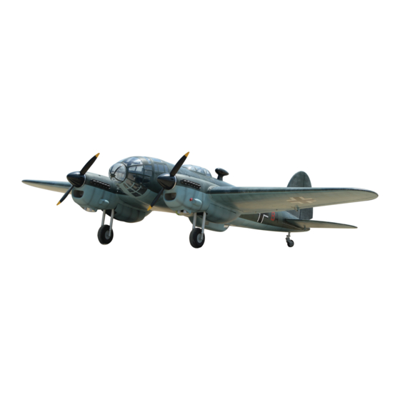
Instruction Manual Book
Glow and EP
ALL BALSA - PLY WOOD CONSTRUCTION.
COVERED IN A HEAT-SHRINK FILM WITH PRINTED.
95% ALMOST READY TO FLY
SPECIFICATION:
- Wingspan: 2,500 mm (98.42 in).
- Length: 1,845 mm (72.63 in).
- Weight: 12.5-13 kg (27.5 – 28.6 lbs).
- Wing area: 106.8dm2.
- Wing loading: 117.04g/dm2.
- Servo mount: size (42 x 21)mm.
- Wing type: Naca airfoils.
- Main gear type: Electric retract gear with
oleo struts for main gear(included).
- Tail gear type: Oleo struts for tail gear
(included).
Item code: BH184
Parts listing required (not included):
- Radio: 08 channels minimum.
- Servo: 9 - 11 standard high torque servos.
- Engine: 20CC GAS (2 pcs).
- Motor: Brushless outrunner 1800-2300W, 450KV.
- Propeller: Suit with your engine.
Recommended Motor
and Battery set up (not included):
- Motor: Admiral GP20 6320-295KV Brushless (2pcs).
- Lipo cell: 6-10 cells 4,000-5,000mAh ( 2 Packs).
- ESC: 80A (2pcs).
- Receiver battery: 6V/7.4V 1200-2000mAh.
Made in Vietnam
Advertisement
Table of Contents

Subscribe to Our Youtube Channel
Related Manuals for Black Horse Model BH184


Summary of Contents for Black Horse Model BH184
- Page 1 Instruction Manual Book Item code: BH184 Glow and EP ALL BALSA - PLY WOOD CONSTRUCTION. COVERED IN A HEAT-SHRINK FILM WITH PRINTED. 95% ALMOST READY TO FLY SPECIFICATION: Parts listing required (not included): - Wingspan: 2,500 mm (98.42 in). - Radio: 08 channels minimum.
-
Page 2: Table Of Contents
Thank you for purchasing Black Horse Model products. With over 18 years experience in production and fly testing, Black Horse Model is committed to bring the best quality products and good service to customers. Along with a team of creative engineers and skilled workers, we will always accompany with customers by our great experiences, fully enthusiasm... -
Page 3: Warranty
In that Black Horse Model has no control over the final assembly or material used for final assembly, SUGGESTION Black Horse Model is not responsible for loss of use , or other incidental or consequential damages. To avoid scratching your new airplane, do not... -
Page 4: Covering Tools
Instruction manual HE-111 Item code: BH184 FLIGHT WARNINGS ADHESIVES AND REQUIRED TOOLS When ready to fly, first extend the transmitter aerial. Thin CA Switch on the transmitter. 30-minute epoxy Switch on the receiver. 6-minute epoxy Check that the wings are correctly fitted to the Threadlocker thread locking cement fuselage. - Page 5 Instruction manual HE-111 Item code: BH184 • Officially designated AMA Air Show Teams (AST) are authorized to use devices and practices as defined within the Team AMA Program Document. (AMA Document #718.) (j) Not operate a turbine-powered aircraft, unless in compliance with the AMA turbine regulations. (AMA Document #510-A.)
-
Page 6: Parts Listing (Not Included)
Instruction manual HE-111 Item code: BH184 PARTS LISTING (NOT INCLUDED) Servo extension leads....2 pcs. 330mm..4 pcs. 190mm ..5 pcs. Propeller: Suit with your engine. Engine: 20 ..2 pcs. LiPo. 6S - 22.2V 3000-5000mAh ..2 Packs Motor: 1800-2300W,450KV ... - Page 7 Instruction manual HE-111 Item code: BH184 : Fuselage (1a,1b: Engin mount; 1c,1d: Motor mount). : Wing (2a: Left wing, 2b: Right wing). : Canopy fuselage ( 3a: front canopy, 3b: main canopy, 3c: top canopy, 3d: Bottom canopy, 3e: Pilot).
- Page 8 Instruction manual HE-111 Item code: BH184 Horn Ball link 44mm Pinned Hinge 3mm Lock Nut - - - 4 - - - 4 - - - 2 - - - 10 3mm Flat Washer 3x12mm Button Head Cap Screw 2.6x1140mm Push rod...
-
Page 9: Installing The Ailerons And Flaps
Instruction manual HE-111 Item code: BH184 INSTALLING THE AILERONS AND FLAPS 44mm Pinned hinge Horn - - - 8 - - - 2 67mm Pinned hinge - - - 6 Bottom view Aileron Flap 67mm Bottom view Cut off shaded portion Ensure smooth, non-binding Apply epoxy glue. -
Page 10: Installing The Ailerons And Flaps Servor
Instruction manual HE-111 Item code: BH184 INSTALLING THE AILERONS AND FLAPS SERVOS block of wood for each of the four mounting screws provided with the servo. 4) Using the thread as a guide and using masking tape, tape the servo lead to the end of the thread: carefully pull the thread out. - Page 11 Instruction manual HE-111 Item code: BH184 Aileron servos. 2 mm approx.16mm 3x12mm 3mm Lock Nut 3mm Flat washer 2x10mm Tp Screw The number of times the same way Assembly Cut off shaded portion Assemble left and right (in this case twice).
- Page 12 Instruction manual HE-111 Item code: BH184 Flaps servos. 2 mm approx.16mm 3x12mm 3mm Lock Nut 3mm Flat washer 3x12mm Button Head 3mm Lock Nut Cap Screw 2x10mm Tp Screw FLAP The number of times the same way Assembly Cut off shaded portion Assemble left and right (in this case twice).
- Page 13 Instruction manual HE-111 Item code: BH184 Bottom view Horn Aileron 3mm Lock Nut 3x12mm Button Head Cap Screw Bottom view 2x10mm Tp Screw Aileron Cut off shaded portion Apply epoxy glue. carefully.
- Page 14 Instruction manual HE-111 Item code: BH184 Flap 3mm Lock Nut 3x12mm Tp Screw Bottom view Flap 2x10mm Tp Screw Flap Bottom view The number of times Assemble left and right sides the same way. the same way Assembly (in this case twice).
-
Page 15: Installing The Engine Mount
Instruction manual HE-111 Item code: BH184 INSTALLING THE MOTOR MOUNT 5x15mm Socket Head 5x16mm Flat washer Cap Screw - - - 8 - - 8 Bottom view 5x16mm Flat washer 5x16mm Flat washer 5x15mm Socket Head 5x15mm Cap Screw Socket Head... -
Page 16: Installing The Main Gear
Instruction manual HE-111 Item code: BH184 INSTALLING THE MAIN GEAR 4x20mm Button Head 4mm Flat washer 4mm Spring Washer Cap Screw - - - - - - - 8 - - - 2 - - - 8 - - - 8... -
Page 17: Installing The Engine Mount
Instruction manual HE-111 Item code: BH184 ELECTRIC RETRACT SYSTEM Main Wheel Power led POWER 7.4v Controller Box Receiver Main Wheel Handle INSTALLING THE MOTOR MOUNT May be you also need to trim some wood from the tri-angle wood for the installation is easy. -
Page 18: Installing The Electric Motor (Ep Version)
Instruction manual HE-111 Item code: BH184 INSTALLING THE ELECTRIC MOTOR (EP VERSION) AND BATTERY 4x15mm Socket M4 Blind Nut Battery Head Cap Screw - - - - - - - - - 8 - - - - - 8 4mm Spring Washer... -
Page 19: Mounting The Cowl
Instruction manual HE-111 Item code: BH184 MOUNTING THE COWL (L. R) 3x12mm TP Screw - - - - 10 - - - - - 2 pcs. Plastic Part (L.R) - - - - - 4 pcs. <Left> Top view Assemble left and right Apply epoxy glue. - Page 20 Instruction manual HE-111 Item code: BH184 3x12mm TP Screw Top view Open Top view Assemble left and right sides the same way.
-
Page 21: Installing The Spinner
Instruction manual HE-111 Item code: BH184 Top view Close INSTALLING THE SPINNER Install the spinner back-plate, propeller and spinner cone. The propeller should not touch any part of the spinner cone. If it dose, use a sharp modeling knife and carefully trim away the spinner cone where the propeller comes in contact with it. -
Page 22: Installing The Gear Door
Instruction manual HE-111 Item code: BH184 INSTALLING THE GEAR DOOR 67mm Pinned hinge 3x12mm Button Head 3mm Flat Washer Cap Screw - - - 16 - - - 8 - - - - 6 - - - 12 3 x 12mm TP Screw 2.6x50mm Push rod... - Page 23 Instruction manual HE-111 Item code: BH184 Bottom view Bottom view 3x12mm TP Screw Cut off shaded portion carefully.
- Page 24 Instruction manual HE-111 Item code: BH184 3mm Lock Nut 3mm Flat Washer 67mm Pinned hinge 3x10mm Button Head Cap Screw Assemble left and right Apply epoxy glue. sides the same way.
- Page 25 Instruction manual HE-111 Item code: BH184 6x136mm Aluminium Collar 3mm Lock Nut 3mm Flat Washer 3x12mm Button Head Cap Screw Bottom view Assemble left and right sides the same way.
- Page 26 Instruction manual HE-111 Item code: BH184 Bottom view INSTALLING THE WING PLASTIC LIGHT - - - - - - - 1 - - - - - - - 1 Top view <L> Top view <L> Cut off shaded portion Apply epoxy glue.
-
Page 27: Installing The Fuselage Servos
Instruction manual HE-111 Item code: BH184 INSTALLING THE FUSELAGE SERVOS 1) Install the rubber grommets and brass collets into the elevator, rudder and throottle servor. Test fit the servos into the servo tray. Trim the tray if necessary to fit your servos. -
Page 28: Installing Horizontal Stabilizer
Instruction manual HE-111 Item code: BH184 INSTALLING HORIZONTAL STABILIZER 1. Using a modeling knife, cut away the covering When you are sure that everything is aligned correctly, mix up a generous amount of 30 minute from the fuselage for the stabilizer and remove it. - Page 29 Instruction manual HE-111 Item code: BH184 340mm 12 Aluminium - - - - - - - - - - - 1 Top view 340mm 12 Aluminium Top view B’ A = A’ B = B’ Apply epoxy glue.
- Page 30 Instruction manual HE-111 Item code: BH184 Horn 3x12mm Button Head 3mm Flat Washer Ball link Cap Screw - - - 4 - - - - 4 - - - 2 - - - 4 - - - 2 3mm Lock Nut 2.6x1140mm Push rod...
-
Page 31: Installing Vertical Stabilizer
Instruction manual HE-111 Item code: BH184 3x12mm Button Head Cap scew Flash washer Push rod Ball link Servo tail 3mm Lock Nut Top view Elevator Servo Elevator Pushrod Elevator servo The number of times Assemble left and right the same way Assembly sides the same way. - Page 32 Instruction manual HE-111 Item code: BH184 INSTALLING THE RUDDER Horn 44mm Pinned Hinge 2.6x1140mm Push rod 3mm Lock Nut - - 1 - - - 2 - - - 3 - - - 1 3x12mm Button Head Ball link 3mm Flat Washer...
- Page 33 Instruction manual HE-111 Item code: BH184 Push rod Ball link Horn Aluminium ball 3mm Lock Nut 3x12mm Horn Button Head Horn Cap Screw Top view 3x12mm Button Head Cap scew Flash washer Push rod Ball link Servo tail 3mm Lock Nut Cut off shaded portion Apply epoxy glue.
-
Page 34: Installing The Tail Gear
Instruction manual HE-111 Item code: BH184 Rudder servo INSTALLING THE TAIL GEAR 1200mm Cable rod Locknut 3mm Hex Nut - - - - - - - 2 - - - - - - - - - - 4 - - - - - - - - 2... - Page 35 Instruction manual HE-111 Item code: BH184 Bottom view 3x15mm Socket Head Cap Screw Secure nylon hinges with instant glue being careful vertical and rudder. 3mm Spring Washer Align the center line of vertical fin with rudder. Bottom view Close/open Bottom view...
-
Page 36: Secure The Wing To The Fulselage
Instruction manual HE-111 Item code: BH184 Servo Gear Tail Gear Cable M3 Metal Clevit 3mm Connector Cab rod Hex Nut Top view SECURE THE WING TO THE FULSELAGE 995mm 32 Aluminium ●Attack the wings to the joiner tube and secure the wing panels to the fuse lage. - Page 37 Instruction manual HE-111 Item code: BH184 Top view 772mm 19 Aluminium 995mm 32 Aluminium Top view...
-
Page 38: Installing The Swich And Receiver, Battery
Instruction manual HE-111 Item code: BH184 3x15mm 3x20mm Socket Head Socket Head Cap Screw Cap Screw 6X50mm Aluminium Top view 2.5mm Hex wrench INSTALLING THE RECEIVER AND BATTERY INSTALLING THE SWITCH 1. Plug the servo leads and the switch lead into the 1. -
Page 39: Installing Canopy Fuselage
Instruction manual HE-111 Item code: BH184 INSTALLING CANOPY FUSELAGE Position the canopy so the rear frame on the canopy is aligned with the rear edge of the cockpit opening. Use canopy glue to secure - - - - 1 - - - - 1 the canopy to the canopy hatch. - Page 40 Instruction manual HE-111 Item code: BH184 Top view Assemble left and right Cut off shaded portion Apply epoxy glue. carefully sides the same way.
-
Page 41: Installing Plastic Fuselage
Instruction manual HE-111 Item code: BH184 INSTALLING PLASTIC FUSELAGE Plastic Fuselage - - - - - - - - - - 1 Top view INSTALLING THE ENGINE MOUNT May be you also need to trim some wood from the tri-angle wood for the installation is easy. -
Page 42: Installing The Engine
Instruction manual HE-111 Item code: BH184 ENGINE-20CC Plate of plywood Throttle hole Φ 6mm 6.2mm 6.2mm INSTALLING THE ENGINE 4mm Lock Nut 4x30mm Socket Head 4mm Flat Washer Cap Screw - - - - - - - - - 8... -
Page 43: Installation The Fuel Tank
Instruction manual HE-111 Item code: BH184 Top view M4 Blind Nut 4x30mm Socket Head Cap Screw 4mm Flat Washer 4mm Spring Washer Top view INSTALLING THE FUEL TANK INSTALLATION THE FUEL TANK 6) When satisfied with the alignment of the stopper... - Page 44 Instruction manual HE-111 Item code: BH184 Clunks Fiber glass - - - 2 - - - 2 - - - 8 - - - 2 - - - 2 - - - 2 - - - 2 INSTALLING THE STOPPER...
- Page 45 Instruction manual HE-111 Item code: BH184 Bottom view Bottom view...
-
Page 46: Installing The Throttle
Instruction manual HE-111 Item code: BH184 3. Slide the adjustable metal connector / servo arm INSTALLING THE THROTTLE assembly over the plain end of the pushrod wire. Position the throttle stick and the throttle trim at their 1. Install one adjustable metal connector through the lowest positions. -
Page 47: Mounting The Cowl
Instruction manual HE-111 Item code: BH184 MOUNTING THE COWL 4. While holding the cowl firmly in position, drill 1. Remove the muffler and needle valve assembly four 1,6mm pilot holes through both the cowl from the engine. Slide the fiberglass cowl over the and the side edges of the firewall. -
Page 48: Balancing
Instruction manual HE-111 Item code: BH184 LATERAL BALANCE BALANCING It is critical that your airplane be balanced After you have balanced a plane on the C.G. correctly. Improper balance will cause your plane to You should laterally balance it. Doing this will lose control and crash. -
Page 49: Pre-Fight Check
Instruction manual HE-111 Item code: BH184 In order to obtain the CG specified, reposition the receiver and other equipment. If not obtain the CG specified, add a weight and adjust. 12mm 12mm Aileron control 14mm 14mm Elevator 25mm Do not fly before confirming the... - Page 50 Instruction manual HE-111 Item code: BH184 FOR YOUR RADIO INSTALLATION BASIC CONNECTION FOR AIRPLANE AND ADJUSTMENT OF SERVOS ● For more information, refer to radio system instruction manual. Example of connection ● Follow instruction manual of Engine and Battery. Engine...
-
Page 51: Main Gear Dimensional Detail
Instruction manual HE-111 Item code: BH184 MAIN GEAR DIMENSIONAL DETAIL 80mm 65.00 45.00 ø16mm 154mm 130.50 TAIL GEAR DIMENSIONAL DETAIL 23mm 31mm 18mm... -
Page 52: Decoration
Instruction manual HE-111 Item code: BH184 DECORATION DECORATION < Top view > < Bottom view > < Side view > Left < Side view > Right... - Page 54 I/C FLYING WARNING Always operate in open areas, away from NEVER fly near power lines,aerials or ALWAYS adjust the engine from behind factories, hospitals, schools, buildings other dangerous areas including airports, the propeller, and do not allow any part NEVER and houses etc.
- Page 55 I/C FLYING GUIDE Operate the control sticks on the ALWAYS land the model INTO When ready to fly, first extend transmitter and check that the th e wind , this en su res tha t th e the transmitter aerial. control surfaces move freely and in model lands at the slowest possible the CORRECT directions.
Need help?
Do you have a question about the BH184 and is the answer not in the manual?
Questions and answers