
Related Manuals for Black Horse Model BH 105


Summary of Contents for Black Horse Model BH 105
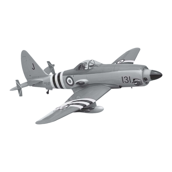
- Page 1 Instruction Manual book ITEM CODE:BH 105. SPECIFICATION Wingspan : 2,240 mm 88.19 in. Length 2,050 mm 80.71 in. Weight 9.3 kg 20.46 Lbs. Radio 08 channels. Servo 10 servos. Engine 50-55CC Made in Vietnam.
- Page 2 WESTLAND WYVERN - Item code:BH105 INSTRUCTION MANUAL. This instruction manual is designed to help you build a great flying aeroplane. Please read this manual thoroughly before starting assembly of your WESTLAND WYVERN Use the parts listing below to identify all parts. WARNING.
-
Page 3: Safety Precaution
WESTLAND WYVERN - Item code:BH105 INSTRUCTION MANUAL. Caution: this model is not a toy! If you are a beginner to this type of powered model, please ask an experienced model flyer for help and support. If you attempt to operate the model without knowing what you are doing you could easily injure yourself or somebody else. -
Page 4: Installing The Aileron Servos
WESTLAND WYVERN - Item code:BH105 INSTRUCTION MANUAL. REPLACEMENT SMALL PARTS 1. Door mounting wheel. 11. Air tanks. 2. Air retract main gear. 12.Air line sets. 3. 3 way connector. 13. Spinner. 4. 4 way connector. 14.Plastic parts of Fuselage 5. Valve one way. 15. -
Page 5: Installing The Aileron Linkages
WESTLAND WYVERN - Item code:BH105 INSTRUCTION MANUAL. 3) Using the thread as a guide and using masking tape, tape the servo lead to the end of the thread: carefully pull the thread out. When you have pulled the servo lead out, re- move the masking tape and the servo lead from the thread. -
Page 6: Installing The Flap Servos
WESTLAND WYVERN - Item code:BH105 INSTRUCTION MANUAL. Secure. Secure. 2. INSTALLING THE FLAP CONTROL HORN. 3mm x 15mm. Repeat the procedure for the other wing half. II. FLAP. 1.INSTALLING THE FLAP SERVOS. Control horn of the flap Flap C/A glue. Electric wire Thread... - Page 7 WESTLAND WYVERN - Item code:BH105 INSTRUCTION MANUAL. INSTALLING THE FLAP LINKAGES. Installing the aileron linkages as pictures below. C/A glue. 2x8 mm. 60 mm Secure. C/A glue. secure C/A glue. Repeat the procedure for the other wing half. INSTALLING AIR RETRACTABLE LANDING GEAR.
- Page 8 WESTLAND WYVERN - Item code:BH105 INSTRUCTION MANUAL.
- Page 9 WESTLAND WYVERN - Item code:BH105 INSTRUCTION MANUAL. 3 x 16mm 3 x 15mm Secure Secure...
- Page 10 WESTLAND WYVERN - Item code:BH105 INSTRUCTION MANUAL. Lock 3 x 16mm Secure Lock . Lock Drill a hole 3.2mm diameter 3x12mm 3x12mm Drill a hole 3.2mm diameter Drill a hole 3.2mm diameter...
- Page 11 WESTLAND WYVERN - Item code:BH105 INSTRUCTION MANUAL. Epoxy glue. 3x12mm Secure Drill a hole 3mm diameter Secure Drill a hole 3mm diameter...
- Page 12 WESTLAND WYVERN - Item code:BH105 INSTRUCTION MANUAL. Mark line. 3x12mm Remove covering Secure Epoxy glue. 3x12mm 3x12mm...
- Page 13 WESTLAND WYVERN - Item code:BH105 INSTRUCTION MANUAL. C/A glue. C/A glue. Mark line. 3x12mm Secure R e m o v e covering Secure Epoxy glue.
-
Page 14: Installing The Engine Mount
WESTLAND WYVERN - Item code:BH105 INSTRUCTION MANUAL. Secure Drill a hole 4mm diameter Front view. INSTALLING THE ENGINE. 5x70mm Bottom side Repeat the procedure for the other wing half. INSTALLING THE ENGINE MOUNT. See pictures below: Secure... -
Page 15: Installing The Throttle - Cable
WESTLAND WYVERN - Item code:BH105 INSTRUCTION MANUAL. INSTALLING THE THROTTLE - CABLE. 1. Install one adjustable metal connector through the third hole out from the center of one servo arm, enlarge the hole in the servo arm using a 2mm drill bit to accommodate the servo connector. -
Page 16: Installing The Stopper Assembly
WESTLAND WYVERN - Item code:BH105 INSTRUCTION MANUAL. Secure FUEL TANK. INSTALLING THE STOPPER ASSEMBLY 1) The stopper has been pre-assembled at the factory. Silicon tube ( not included) 2) Using a modeling knife, cut one length Fuel pick- up tube of silicon fuel line (the length of silicon fuel line Vent tube is calculated by how the weighted clunk should... - Page 17 WESTLAND WYVERN - Item code:BH105 INSTRUCTION MANUAL. Do not secure the tank into place perma- Left side. nently until after balancing the airplane. You may need to remove the tank to mount the battery in the fuel tank compartment R e m o v e covering Secure.
- Page 18 WESTLAND WYVERN - Item code:BH105 INSTRUCTION MANUAL. Secure. Bottom side. Trim and cut Secure. 2. While keeping the back edge of the cowl flush with the marks, align the front of COWLING. the cowl with the crankshaft of the engine. The front of the cowl should be positioned so the 1.
- Page 19 WESTLAND WYVERN - Item code:BH105 INSTRUCTION MANUAL. Drill 2.5mm hole. Drill 2.5mm hole. Drill 2.5mm hole. Mark point.
- Page 20 WESTLAND WYVERN - Item code:BH105 INSTRUCTION MANUAL. Secure Mark point. Mark point. Drill 2.5mm hole. Drill 2.5mm hole. Secure. 3x12mm...
-
Page 21: Horizontal Stabilizer
WESTLAND WYVERN - Item code:BH105 INSTRUCTION MANUAL. Left side. M a c h i n e screw. M a c h i n e screw. Bottom side. HORIZONTAL STABILIZER. See pictures below: Front view. 3x15mm INSTALLING THE SPINNER. Install the spinner backplate, propeller and spinner cone. -
Page 22: Elevator Control Horn Installation
WESTLAND WYVERN - Item code:BH105 INSTRUCTION MANUAL. 2x10mm. 3 x15mm Secure. Secure ELEVATOR CONTROL HORN INSTALLATION. Elevator control horn install as same as the way of aileron control horn. Please see pic- tures below. Secure 3x20mm Bottom side. - Page 23 WESTLAND WYVERN - Item code:BH105 INSTRUCTION MANUAL. Mark line. Elevator control horn. ELEVATOR PUSHROD HORN INSTALLATION. 2x8 mm. Mark line. 95 mm Secure. R e m o v e covering Secure Bottom side. Elevator pushrod Elevator pushrod...
-
Page 24: Mounting The Tail Wheel Bracket
WESTLAND WYVERN - Item code:BH105 INSTRUCTION MANUAL. Epoxy glue. MOUNTING THE TAIL WHEEL BRACKET. Epoxy glue. 3x15mm C/A glue. Bottom side. - Page 25 WESTLAND WYVERN - Item code:BH105 INSTRUCTION MANUAL. Plastic part for tail gear R e m o v e covering.
- Page 26 WESTLAND WYVERN - Item code:BH105 INSTRUCTION MANUAL. E p o x y Mark line. glue. Mark line. C/A glue. C/A glue. R e m o v e covering. R e m o v e covering.
-
Page 27: Vertical Installation
WESTLAND WYVERN - Item code:BH105 INSTRUCTION MANUAL. Aluminium 167 mm VERTICAL INSTALLATION. Rudder servo install as same as method of elevator servo. See picture below: RUDDER CONTROL HORN INSTALLA- TION. Rudder control horn install as same as the way of aileron control horn. Please see pic- tures below. - Page 28 WESTLAND WYVERN - Item code:BH105 INSTRUCTION MANUAL. Rudder Control horn. 3x15mm 2x8 mm. 115 mm Secure Secure Secure Bottom side. INSTALLATION SERVO USING FOR VALUE CONTROL...
- Page 29 WESTLAND WYVERN - Item code:BH105 INSTRUCTION MANUAL. INSTALLATION SERVO AIR RETRACT- ABLE LANDING GEAR . Air tank Valve control Secure. Secure. INSTALLATION AIR TANK Air tank Left main Right main Tie wrap. gear wing gear wing...
-
Page 30: Installing The Switch
WESTLAND WYVERN - Item code:BH105 INSTRUCTION MANUAL. UBEC Battery. Switch . INSTALLING THE SWITCH. 1) Cut out the switch hole using a modeling Receiver. knife. Use a 2mm drill bit and drill out the two mounting holes through the fuselage side. 2) Secure the switch in place using the two machine screws provided with the radio system. -
Page 31: Wing Attachment
WESTLAND WYVERN - Item code:BH105 INSTRUCTION MANUAL. Right wing. Epoxy glue. See picture wing attach to fuselage. C/A glue. Wing bolt. WING ATTACHMENT. Locate the aluminium wing dihedral brace. 875mm *** Test fit the aluminium tube dihedral brace 4 x 40mm into each wing haft. - Page 32 WESTLAND WYVERN - Item code:BH105 INSTRUCTION MANUAL. Secure Drill a hole 3mm diameter Plastic part bottom side fuselage Secure Left wing. Drill a hole 3mm diameter...
- Page 33 WESTLAND WYVERN - Item code:BH105 INSTRUCTION MANUAL. Accurately mark the balance point on the top Epoxy glue. of the wing on both sides of the fuselage. The balance point is located 157mm back from the leading edge. This is the balance point at which your model should balance for your first flights.
-
Page 34: Control Throws
WESTLAND WYVERN - Item code:BH105 INSTRUCTION MANUAL. CONTROL THROWS. 1) We highly recommend setting up a plane using the control throws listed. 2) The control throws should be meas- ured at the widest point of each control sur- face. 3) Check to be sure the control surfaces move in the correct directions.
Need help?
Do you have a question about the BH 105 and is the answer not in the manual?
Questions and answers