Table of Contents
Advertisement
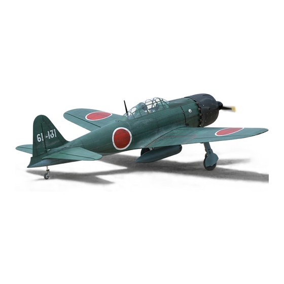
A6M ZERO
Glow and EP
ALL BALSA - PLY WOOD CONSTRUCTION.
COVERED IN A HEAT-SHRINK FILM WITH PRINTED.
95% ALMOST READY TO FLY
SPECIFICATION:
- Wingspan: 2,385 mm (94 in).
- Length: 2,059 mm (81 in).
- Weight: 10.8 kg (24 lbs).
- Wing area: 99.5 dm2.
- Wing loading: 108.5 g/dm2.
- Wing type: Naca Airfoil.
- Servo mount: 42mm x 21mm.
- Main gear type: Electric retract gear with
oleo struts for main gear(included).
- Tail gear type: Oleo struts for tail gear (included).
Instruction Manual Book
Item code: BH180
Parts listing required (not included):
- Radio: min 07 channels.
- Servo: 8 standard high torque servos.
- Engine: 60 cc gas.
- Motor: Brushless outrunner 5000 - 6500W, 230KV.
- Propeller: Suit with your engine.
Recommended motor and battery set up
(not included):
- Motor: RIMFIRE. 50 cc.
- Lipo cell: 12 cells 5500 - 6000mAh.
- Receiver battery: 6.0V 2400-2600mAh(2 Packs).
- ESC: 120A.
Made in Vietnam.
Advertisement
Table of Contents

Related Manuals for Black Horse Model A6M ZERO BH180


Summary of Contents for Black Horse Model A6M ZERO BH180
- Page 1 Instruction Manual Book Item code: BH180 A6M ZERO Glow and EP ALL BALSA - PLY WOOD CONSTRUCTION. COVERED IN A HEAT-SHRINK FILM WITH PRINTED. 95% ALMOST READY TO FLY SPECIFICATION: Parts listing required (not included): - Wingspan: 2,385 mm (94 in). - Radio: min 07 channels.
-
Page 2: Table Of Contents
Thank you for purchasing Black Horse Model products. With over 19 years experience in production and fly testing, Black Horse Model is committed to bring the best quality products and good service to customers. Along with a team of creative engineers and skilled workers, we will always accompany with customers by our great experiences, fully enthusiasm... -
Page 3: Warranty
In that Black Horse Model has no control over the final assembly or material used for final assembly, SUGGESTION Black Horse Model is not responsible for loss of use , or other incidental or consequential damages. To avoid scratching your new airplane, do not... -
Page 4: Covering Tools
INSTRUCTION MANUAL A6M ZERO Item code: BH180 FLIGHT WARNINGS ADHESIVES AND REQUIRED TOOLS When ready to fly, first extend the transmitter aerial. Thin CA Switch on the transmitter. 30-minute epoxy Switch on the receiver. 6-minute epoxy Check that the wings are correctly fitted to the Threadlocker thread locking cement fuselage. - Page 5 INSTRUCTION MANUAL A6M ZERO Item code: BH180 • Officially designated AMA Air Show Teams (AST) are authorized to use devices and practices as defined within the Team AMA Program Document. (AMA Document #718.) (j) Not operate a turbine-powered aircraft, unless in compliance with the AMA turbine regulations. (AMA Document #510-A.) 3.
-
Page 6: Part Listing ( Not Included )
INSTRUCTION MANUAL A6M ZERO Item code: BH180 PARTS LISTING (NOT INCLUDED). Servo extension leads....pcs. 330mm ..2 pcs. 190mm ..2 pcs. Propeller: Suit with your engine. Engine: 55 - 61..1 pcs. LiPo. 6S - 22.2V 300-5000mAh ..2 Packs Motor: 50cc ... - Page 7 INSTRUCTION MANUAL A6M ZERO Item code: BH180 : Fuselage set(1a: Cockpit; 1b: Pilot; : Engine set. : Cowling set. 1c: Canopy; 1d: Plastic). : Electric motor set. : Tail gear set. : Wing set (2a; 2b; 2c: Aluminium tube dihedral brace). : Plastic part set.
-
Page 8: Installing The Ailerons And Flaps
INSTRUCTION MANUAL A6M ZERO Item code: BH180 INSTALLING THE AILERONS AND FLAPS. 3x12mm Tp Screw 3x12mm 44mm Pinned hinge - - - - - - - 2 - - - - - - - 10 Tp Screw Horn 67mm Pinned hinge - - - 2 - - - - - - - 8 Bottom View... -
Page 9: Installing The Ailerons And Flap Servos
INSTRUCTION MANUAL A6M ZERO Item code: BH180 INSTALLING THE AILERONS AND FLAPS SERVOS. Place the servo into the servo tray. Center the servo within the tray and drill 1.5mm pilot holes through the block of wood for each of the four mounting screws provided with the servo. Using the thread as a guide and using masking tape, tape the servo lead to the end of the thread: carefully pull the thread out. - Page 10 INSTRUCTION MANUAL A6M ZERO Item code: BH180 Flaps servos. 2 mm approx.16mm 3x12mm Cap Screw 3mm Flat Washer 3mm Hex Nut Screw 3x12mm Tp Screw 2x10mm Tp Screw 1.5mm 1.5mm...
- Page 11 INSTRUCTION MANUAL A6M ZERO Item code: BH180 Aileron servos. 2 mm approx.16mm 3mm Flat Washer 3mm Hex Nut 3x12mm Cap Screw 1.5mm Screw 2x10mm Tp Screw 1.5mm Cut off shaded portion Drill holes using the stated. carefully. (in this case 1.5mm 1.5mm The number of times Assemble left and right...
- Page 12 INSTRUCTION MANUAL A6M ZERO Item code: BH180 Bottom View 2x10mm Aileron 3x15mm Tp Screw Horn 3x12mm Cap Screw C . A C . A Cut off shaded portion carefully. Apply epoxy glue. Apply instant glue (C.A glue, super glue). C . A Assemble left and right sides the same way.
-
Page 13: Installing The Air Retractable Landing Gear
INSTRUCTION MANUAL A6M ZERO Item code: BH180 Top View Bottom View INSTALLING THE AIR RETRACTABLE LANDING GEAR 4x20mm Socket Head 2x10mm Tp Screw 6x55mm Socket Head 3x16mm Button Head - - - - - 8 Cap Screw Cap Screw Cap Screw - - - - - 8 - - - - - 2 - - - - - 4... - Page 14 INSTRUCTION MANUAL A6M ZERO Item code: BH180 Using a modeling knife, carefully 3x4mm Set Screw remove the firm covering from the wing gear tray. Make sure that you do not remove any wood. for Fuselage for Wing 4x20mm Socket Head Cap Screw 4mm Spring Washer 4mm Flat washer...
- Page 15 INSTRUCTION MANUAL A6M ZERO Item code: BH180 6x55mm Socket Head Cap Screw 6mm Flat washer 3x20mm Button Head Cap Screw 3x16mm Button Head Cap Screw...
- Page 16 INSTRUCTION MANUAL A6M ZERO Item code: BH180 Bottom View 2x10 mm Tp Screw Cut off shaded portion carefully. Apply instant glue (C.A glue, super glue). C . A Assemble left and right sides the same way.
-
Page 17: Installing The Fuselage Servos
INSTRUCTION MANUAL A6M ZERO Item code: BH180 INSTALLING THE FUSELAGE SERVOS 1) Install the rubber grommets and brass collets into the elevator, rudder and throottle servor. Test fit the servos into the servo tray. Trim the tray if necessary to fit your servos. 2) Mount the servo to the tray using the mounting screws provided with your radio system. - Page 18 INSTRUCTION MANUAL A6M ZERO Item code: BH180 Bottom View...
- Page 19 INSTRUCTION MANUAL A6M ZERO Item code: BH180 Bottom View Ball link Push rod Aluminium ball 2.6x900mm Push rod 3mm Hex Nut 3x12mm Cap Washer Horn...
- Page 20 INSTRUCTION MANUAL A6M ZERO Item code: BH180 3x12mm Cap scew Flash washer Push rod Ball link Servo tail 3mm Hex nut Top View Elevator servo...
-
Page 21: Installing Vertical Stabilizer
INSTRUCTION MANUAL A6M ZERO Item code: BH180 INSTALLING VERTICAL STABILIZER Ball link 2.6x870mm Push rod - - - 2 - - 1 3x12mm Cap Screw - - - - - - 2 3mm Flat Washer - - - - - 1 Horn - - - - - 2 3mm Hex Nut... - Page 22 INSTRUCTION MANUAL A6M ZERO Item code: BH180 Bottom View Ball link Push rod Aluminium ball 3mm Hex Nut 3x12mm Cap Washer Horn...
- Page 23 INSTRUCTION MANUAL A6M ZERO Item code: BH180 3x12mm Cap scew Flash washer Push rod Ball link Servo tail 3mm Hex nut Top View Rudder servo Rudder...
-
Page 24: Installing The Tail Gear
INSTRUCTION MANUAL A6M ZERO Item code: BH180 INSTALLING THE TAIL GEAR 1200mm Cable rod M3 Metal Clevis 3x16mm Cap Screw - - - - - 2 - - - - - - - 4 - - - - - - - 2 Locknut - - - - - - - - - 4 3x30mm Connector 3mm Flat Washer... - Page 25 INSTRUCTION MANUAL A6M ZERO Item code: BH180 Bottom View M3 Metal Clevit 3mm Connector Cab rod Hex Nut Rudder servo...
- Page 26 INSTRUCTION MANUAL A6M ZERO Item code: BH180...
-
Page 27: Installing The Engine Mount
INSTRUCTION MANUAL A6M ZERO Item code: BH180 INSTALLING THE ENGINE MOUNT May be you also need to trim some wood from the tri-angle Using plate of plywood (supplied with the kit) mark the holes wood for the installation is easy. onto the fire wall for installing the engine mount for DLE-55CC or OS-60CC. -
Page 28: Installing The Stopper
INSTRUCTION MANUAL A6M ZERO Item code: BH180 INSTALLING THE STOPPER Cut off shaded portion... -
Page 29: Installing The Fuel Tank
INSTRUCTION MANUAL A6M ZERO Item code: BH180 INSTALLING THE FUEL TANK Be sure to equip Not included. air vent pipe. Tygon tubing (Gas). And silicone tubing (Methanol). The stopper has been pre-assembled at the To carburetor factory. fuel inlet Tubing for re-fuelling 2) Using a modeling knife, cut one length of silicon fuel line (the length of silicon fuel line is calculated by... -
Page 30: Installing The Engine
INSTRUCTION MANUAL A6M ZERO Item code: BH180 INSTALLING THE ENGINE 5x100mm Socket Head 5x16mm Plastic Washer Connector Cap Screw - - - - - - 1 - - - - - - 4 - - 4 12x65mm Aluminum 5mm Flat washer - - - 4 - - - - - - - - 4 M5 Blind Nut... -
Page 31: Installing The Throttle
INSTRUCTION MANUAL A6M ZERO Item code: BH180 INSTALLING THE THROTTLE direction. When the throttle stick is moved forward from idle to full throttle, the throttle barrel should also open and close using this motion. If not, reverse the direction of the servo, using the Connector - - - - 1 transmitter. -
Page 32: Mounting The Cowl
INSTRUCTION MANUAL A6M ZERO Item code: BH180 MOUNTING THE COWL Mounting part - - - - - 5 Exhaust Pipe - - - - - 1 - - - - - 1 - - - - - 5 3x12mm Tp Screw - - - - - 10 3x15mm Tp Screw - - - - - 7... - Page 33 INSTRUCTION MANUAL A6M ZERO Item code: BH180 3x12mm Tp Screw plastic...
-
Page 34: Installing The Switch, Receiver And Battery
INSTRUCTION MANUAL A6M ZERO Item code: BH180 3x12mm Tp Screw INSTALLING THE SWITCH, RECEIVER AND BATTERY 1) Plug the servo leads and the switch lead into INSTALLING THE SWITCH the receiver. You may want to plug an aileron 1) The switch should be mounted on the fuselage extension into the receiver to make plugging in the side, opposite the muffler, close enough to the aileron servo lead easier when you are installing... -
Page 35: Installing Cockpit Fuselage
INSTRUCTION MANUAL A6M ZERO Item code: BH180 Electric Retract Landing Gear Controller - - - - - 1 Switch Receiver INSTALLING COCKPIT FUSELAGE Position the canopy so the rear frame on the canopy is aligned with the rear edge of the cockpit opening. Use canopy glue to secure the canopy to the canopy hatch. - Page 36 INSTRUCTION MANUAL A6M ZERO Item code: BH180 Top View...
- Page 37 INSTRUCTION MANUAL A6M ZERO Item code: BH180 Top View Must be purchased separately!
-
Page 38: Installing The Wing To The Fuselage
INSTRUCTION MANUAL A6M ZERO Item code: BH180 INSTALLING THE WING TO THE FUSELAGE 32x780mm Aluminium tube. - - - - 1 - - - - - 1 - - - - - 1 Bottom View Apply epoxy glue. - Page 39 INSTRUCTION MANUAL A6M ZERO Item code: BH180 Bottom View Top View Test fit the aluminium tube dihedral brace into each wing haft. The brace should slide in easily. If not, use 220 grit sand around the edges and ends of the brace until it fits properly.
-
Page 40: Installing The Propeller
INSTRUCTION MANUAL A6M ZERO Item code: BH180 Top View Main wing must be inserted and attached completely before fixing with screw. INSTALLING THE PROPELLER 3x12mm TP Scew - - - 4 - - - 1 - - - 1... -
Page 41: Installing The Plastic Part
INSTRUCTION MANUAL A6M ZERO Item code: BH180 INSTALLING THE PLASTIC PART 4x12mm Button Head Cap Screw - - - - 4 - - - - 1 4mm Spring Washer - - - - 1 - - - - 4 4x12mm Button Head Cap Screw Spring Washer... - Page 42 INSTRUCTION MANUAL A6M ZERO Item code: BH180 4x12mm Button Head Cap Screw Spring Washer...
-
Page 43: Installing The Electric Motor
INSTRUCTION MANUAL A6M ZERO Item code: BH180 INSTALLING THE ELECTRIC MOTOR INSTALLING THE ELECTRIC MOTOR (EP VERSION) M4 Blind Nut 10x20mm Aluminum - - - - - 4 4x35mm Socket Head Cap Screw - - 4 4mm Plastic Washer - - - - - 4 M4 Blind Nut - - - - - - - 4 4mm Spring Washer... - Page 44 INSTRUCTION MANUAL A6M ZERO Item code: BH180 Zip tie 5x16mm Plastic Washer 12x70mm Aluminum 5mm Spring Washer 5mm Flat washer 5x100mm Socket Head Cap Screw ???mm...
-
Page 45: Balancing
INSTRUCTION MANUAL A6M ZERO Item code: BH180 BALANCING LATERAL BALANCE It is critical that your airplane be balanced After you have balanced a plane on the C.G. correctly. Improper balance will cause your plane to You should laterally balance it. Doing this will lose control and crash. -
Page 46: Control Throws
INSTRUCTION MANUAL A6M ZERO Item code: BH180 In order to obtain the CG specified, reposition Bottom View the receiver and other equipment. If not obtain the CG specified, add a weight and adjust. 14mm Do not fly before confirming the 14mm Aileron control correct location of the CG. - Page 48 INSTRUCTION MANUAL A6M ZERO Item code: BH180 FOR YOUR RADIO INSTALLATION BASIC CONNECTION FOR AIRPLANE AND ADJUSTMENT OF SERVOS For more information, refer to radio system instruction manual. Example of connection Follow instruction manual of Engine and Battery. Aileron Servo Aileron Aileron Servo Aileron...
-
Page 49: Main Gear Dimensional Detail
INSTRUCTION MANUAL A6M ZERO Item code: BH180 MAIN GEAR DIMENSIONAL DETAIL 19.00 65.00 45.00 130.50 TAIL GEAR DIMENSIONAL DETAIL 23mm 31mm 18mm... - Page 50 I/C FLYING WARNINGS Always operate in open areas, away from fly near power lines,aerials or AL WAYS adjust the engine from behind NEVER factories, hospitals, schools, buildings other dangerous areas including airports, the propeller, and do not allow any part of and houses etc.
- Page 51 I/C FLYING GUIDELINES Operate the control sticks on the ALWAYS land the model INTO When ready to fly, first extend transmitter and check that the the wind, this ensures that the the transmitter aerial. control surfaces move freely and in model lands at the slowest possible the CORRECT directions.
Need help?
Do you have a question about the A6M ZERO BH180 and is the answer not in the manual?
Questions and answers