Table of Contents
Advertisement
Quick Links
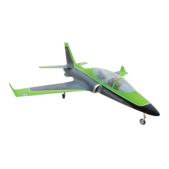
VIPER JET TURBINE
ALL BALSA - PLY WOOD CONSTRUCTION
COVERED IN A HEAT-SHRINK FILM WITH PRINTED.
95% ALMOST READY TO FLY
SPECIFICATION:
- Wingspan: 2000 mm (78.7 in).
- Length: 1820 mm (71.65 in).
- Weight: 9.8 – 10.5 kg (21.6 - 23 lbs).
- Wing area: 62.2 dm2.
- Wing loading: 157.5 g/dm2.
- Wing type: Naca Airfoil.
- Gear type: Electric Retract Gear (included)
with controller box (included).
Instruction Manual Book
Item code: BH181
Parts listing required (not included):
- Radio: 8 channels minimum.
- Servo: 8 servos , size: (35 x 15)mm.
- Engine: Turbine Jet Engine with thrust 8kg
(not included).
Recommended Battery set up (not included):
- Battery receiver:
2S- 7.4V - 3,200mAh.
2S- 4V - 2,200mAh.
Made in Vietnam.
Advertisement
Table of Contents

Related Manuals for Black Horse Model VIPER JET TURBINE


Summary of Contents for Black Horse Model VIPER JET TURBINE
- Page 1 Instruction Manual Book Item code: BH181 VIPER JET TURBINE ALL BALSA - PLY WOOD CONSTRUCTION COVERED IN A HEAT-SHRINK FILM WITH PRINTED. 95% ALMOST READY TO FLY SPECIFICATION: Parts listing required (not included): - Wingspan: 2000 mm (78.7 in). - Radio: 8 channels minimum.
-
Page 2: Table Of Contents
Thank you for purchasing Black Horse Model products. With over 18 years experience in production and fly testing, Black Horse Model is committed to bring the best quality products and good service to customers. Along with a team of creative engineers and skilled workers, we will always accompany with customers by our great experiences, fully enthusiasm... -
Page 3: Warranty
In that Black Horse Model has no control over the final assembly or material used for final assembly, SUGGESTION Black Horse Model is not responsible for loss of use , or other incidental or consequential damages. To avoid scratching your new airplane, do not... -
Page 4: Covering Tools
Viper Jet TURBINE Item code: BH181 Instruction Manual FLIGHT WARNINGS ADHESIVES AND REQUIRED TOOLS When ready to fly, first extend the transmitter aerial. Thin CA Switch on the transmitter. 30-minute epoxy Switch on the receiver. 6-minute epoxy Check that the wings are correctly fitted to the Threadlocker thread locking cement fuselage. - Page 5 Viper Jet TURBINE Item code: BH181 Instruction Manual • Officially designated AMA Air Show Teams (AST) are authorized to use devices and practices as defined within the Team AMA Program Document. (AMA Document #718.) (j) Not operate a turbine-powered aircraft, unless in compliance with the AMA turbine regulations. (AMA Document #510-A.)
-
Page 6: Parts Listing (Not Included)
Viper Jet TURBINE Item code: BH181 Instruction Manual PARTS LISTING (NOT INCLUDED). Servo extension leads....pcs. 920mm ..3 pcs. 330mm ..2 pcs. Turbine Jet Engine with thrust 8kg 220mm ..9 pcs. 420mm ..4 pcs. LiPo: 2S- 7.4V - 3,200mAh....2 Packs LiPo: 2S- 4V - 2,200mAh....2 Packs... - Page 7 Viper Jet TURBINE Item code: BH181 Instruction Manual 1: Fuselage set. 2: Wing set. 3: Horizontal stabilizer set 4: Vertical stabilizer set. 5: Nose gear set . 6: Main gear set. 7: Fuel tank set. 8: Engine set. 9: CG set.
-
Page 8: Installing The Ailerons And Flaps
Viper Jet TURBINE Item code: BH181 Instruction Manual INSTALLING THE AILERONS AND FLAPS 44mm Pinned Hinge Aileron 3x12mm Tp Screw - - - 6 - - - 4 67mm Pinned Hinge Flap Horn - - - 6 - - - 2... - Page 9 Viper Jet TURBINE Item code: BH181 Instruction Manual Bottom view 6x50mm Aluminium Apply threadlocker Assemble left and right (screw cement). sides the same way.
-
Page 10: Installing The Aileron And Flap Servo
Viper Jet TURBINE Item code: BH181 Instruction Manual INSTALLING THE AILERON AND FLAP SERVOS 2.6x55mm Pushrod Flap 3x12mm Button Head 2x10mm Tp Screw - - - 2 Cap Screw - - - 16 - - - 8 2.6x65mm Pushrod Aileron... - Page 11 Viper Jet TURBINE Item code: BH181 Instruction Manual For Flap Servo 2.6x55mm Pushrod Lock Nut Flat Washer 3x12mm Button Head Cap Screw 2x10mm Tp Screw 3x12mm Button Head Cap Screw 2x10mm Tp Screw Must be purchased Assemble left and right separately! sides the same way.
- Page 12 Viper Jet TURBINE Item code: BH181 Instruction Manual For Aileron Servo 3mm Flat Washer 3x12mm Button Head Cap Screw 3mm Lock Nut 2x10mm Tp Screw 2x10mm Tp Screw Must be purchased Assemble left and right The number of times separately! sides the same way.
- Page 13 Viper Jet TURBINE Item code: BH181 Instruction Manual Aileron 3x12mm Tp Screw Horn 3x12mm Button Head Cap Screw C . A C . A Apply instant glue Cut off shaded portion (C.A glue, super glue). carefully. C . A The number of times...
-
Page 14: Installing The Main Landing Gear
Viper Jet TURBINE Item code: BH181 Instruction Manual INSTALLING THE MAIN LANDING GEAR 4x16mm Socket Head Cap Screw - - - 8 4mm Spring Washer - - - 8 - - - 1 - - - 1 Bottom view Brake Wire... - Page 15 Viper Jet TURBINE Item code: BH181 Instruction Manual Bottom view Assemble left and right sides the same way.
- Page 16 Viper Jet TURBINE Item code: BH181 Instruction Manual Bottom view Apply instant glue (C.A glue, super glue). C . A...
- Page 17 Viper Jet TURBINE Item code: BH181 Instruction Manual Assemble left and right sides the same way.
-
Page 18: Installing The Plastic Part For Wings
Viper Jet TURBINE Item code: BH181 Instruction Manual INSTALLING THE PLASTIC PART FOR WINGS Plastic Light - - - 2 Plastic Light Cover Wing Tip - - - 2 - - - 1 Top view Apply instant glue Assemble left and right (C.A glue, super glue). - Page 19 Viper Jet TURBINE Item code: BH181 Instruction Manual Top view Wing tip Left Right Assemble left and right Apply instant glue sides the same way. (C.A glue, super glue). C . A...
-
Page 20: Installing Horizontal Stabilizer
Viper Jet TURBINE Item code: BH181 Instruction Manual INSTALLING THE HORIZONTAL STABILIZER 44mm Pinned hinge Bottom view - - - 8 6x50mm Aluminium - - - 2 44mm 6x50mm Aluminium INSTALLING THE HORIZONTAL STABILIZER SERVOS 2x10mm Tp Screw Horn 3x12mm Button Head... - Page 21 Viper Jet TURBINE Item code: BH181 Instruction Manual Bottom view 2 mm approx.16mm 2x10mm TpScrew 1.5 mm Screw 2 m m 1.5 mm 1.5 mm Set all scerws securely. If they come off during flight Warning you will lose control of your aircraft!
-
Page 22: Installing The Horizontal Stabilizer Linkages
Viper Jet TURBINE Item code: BH181 Instruction Manual INSTALLING THE HORIZONTAL STABILIZER LINKAGES Ball link Aluminium ball 3X12mm Button Head Cap Screw Flat Washer 3mm Lock Nut The number of times Assemble left and right Apply epoxy glue. the same way Assembly sides the same way. -
Page 23: Installing The Vertical Stabilizer
Viper Jet TURBINE Item code: BH181 Instruction Manual INSTALLING THE VERTICAL STABILIZER 44mm Pinned hinge 6x50mm Aluminium Bottom view - - - 4 - - - 1 44mm 6x50mm Aluminium The number of times Apply threadlocker Assemble left and right the same way Assembly (screw cement). -
Page 24: Installing The Vertical Stabilizer Servo
Viper Jet TURBINE Item code: BH181 Instruction Manual INSTALLING THE VERTICAL STABILIZER SERVOS 3x12mm Button Head 2x10mm Tp Screw Horn Cap Screw - - - 4 - - - 1 - - - 2 Ball Link 3mm Lock Nut - - - 2... - Page 25 Viper Jet TURBINE Item code: BH181 Instruction Manual 2 mm approx.16mm 2x10mm TpScrew 1.5 mm Screw 2 m m 1.5 mm 1.5 mm Set all scerws securely. If they come off during flight Warning you will lose control of your aircraft! Bottom view Drill holes using the stated.
-
Page 26: Installing The Vertical Stabilizer Linkages
Viper Jet TURBINE Item code: BH181 Instruction Manual INSTALLING THE VERTICAL STABILIZER LINKAGES Ball link Aluminium ball 3X12mm Button Head Cap Screw Flat Washer 3mm Lock Nut Assemble left and right The number of times Apply epoxy glue. sides the same way. -
Page 27: Installing The Fuselage
Viper Jet TURBINE Item code: BH181 Instruction Manual INSTALLING THE FUSELAGE Top view Ø12x205mm Aluminium Tube - - - 3 4x12mm Socket Head Cap Screw - - - 4 4mm Lock Nut - - - 4 4mm Flat Washer - - - 8 Ø12x205mm Aluminium Tube... - Page 28 Viper Jet TURBINE Item code: BH181 Instruction Manual Plastic air intake - - - 1 Top view Assemble left and right The number of times sides the same way. the same way Assembly (in this case twice).
-
Page 29: Installing The Wings To The Fuselage
Viper Jet TURBINE Item code: BH181 Instruction Manual INSTALLING THE WING TO FUSELAGE Ø20x819mm Carbon Tube - - - 1 Top view... -
Page 30: Installing The The Horizontal & Vertical Stabilizer To Fuselage
Viper Jet TURBINE Item code: BH181 Instruction Manual Top view INSTALLING THE HORIZONTAL & VERTICAL STABILIZER TO FUSELAGE Ø12x412mm Carbon Tube - - - 1 12x166mm Carbon Tube Ø12x166mm Carbon Tube - - - 1 Plywood part for rudder stab... - Page 31 Viper Jet TURBINE Item code: BH181 Instruction Manual 600 Deg High Temperature Braided Soft Chemical Fiber Tubing Servo extension lead Top view...
- Page 32 Viper Jet TURBINE Item code: BH181 Instruction Manual Top view Secure Plywood part for rudder stab Apply instant glue Cut off shaded portion (C.A glue, super glue). carefully. C . A...
- Page 33 Viper Jet TURBINE Item code: BH181 Instruction Manual Ply Wood part for the rear bottom fuselage Bottom view Cut off shaded portion Apply epoxy glue. carefully.
-
Page 34: Installing The Nose Gear Retract
Viper Jet TURBINE Item code: BH181 Instruction Manual INSTALLING THE NOSE GEAR RETRACT 3x8mm Button Head Cap Screw 4x16mm Button Head Cap Screw - - - 4 - - - 4 4mm Flat Washer 3x12mm Button Head Cap Screw - - - 4... - Page 35 Viper Jet TURBINE Item code: BH181 Instruction Manual Nose gear retract servos. 2 mm approx.16mm 3x8mm Button Head Cap Screw Bottom view Cut off shaded portion Drill holes using the stated. Pay close attention here. carefully. (in this case 1.5mm...
- Page 36 Viper Jet TURBINE Item code: BH181 Instruction Manual 3x12mm Button Head Cap Screw Flat Washer Lock Nut Bottom view...
-
Page 37: Installing The Engine
Viper Jet TURBINE Item code: BH181 Instruction Manual INSTALLING THE ENGINE Exhaust tube 3x15mm Tp Screw - - - 10 - - - 1 Top Hatch Open and Close Top view Must be purchased separately! - Page 38 Viper Jet TURBINE Item code: BH181 Instruction Manual 10mm Engine Top view 3x15mm Tp Screw 3x15mm Tp Screw Must be purchased separately!
-
Page 39: Installing The Fuel Tank
Viper Jet TURBINE Item code: BH181 Instruction Manual INSTALLING THE FUEL TANK INSTALLING THE STOPPER Cut off shaded portion carefully. - Page 40 Viper Jet TURBINE Item code: BH181 Instruction Manual Stopper Fuel Tank 1 - - - 1 - - - 1 Clunks - - - 1 Top view Fuel Tank 1 Tygon Tubing Must be purchased separately!
- Page 41 Viper Jet TURBINE Item code: BH181 Instruction Manual Tygon Tubing Fuel Tank 2 Zip tie Top view Must be purchased separately!
-
Page 42: Installing The Receiver, Battery, Controller Box And Switch
Viper Jet TURBINE Item code: BH181 Instruction Manual Top view Smoke tank Tygon Tubing Plywood (already remove in page 37) Screw (already remove in page 37) INSTALLING THE RECEIVER, BATTERY, CONTROLLER BOX AND SWITCH Controller Box - - - 1... -
Page 43: Installing Cockpit Fuselage
Viper Jet TURBINE Item code: BH181 Instruction Manual Top view Controller Box LED Controller Brushless Fuel Pump Receiver Battery Battery INSTALLING THE COCKPIT FUSELAGE Position the canopy so the rear frame Control gear Canopy on the canopy is aligned with the rear edge of the cockpit opening. - Page 44 Viper Jet TURBINE Item code: BH181 Instruction Manual Top view Adhesive tape Apply epoxy glue.
-
Page 45: Balacing
Viper Jet TURBINE Item code: BH181 Instruction Manual LATERAL BALANCE BALANCING 1. It is critical that your airplane be balanced correctly. After you have balanced a plane on the C.G. Improper balance will cause your plane to lose You should laterally balance it. Doing this will control and crash. - Page 46 Viper Jet TURBINE Item code: BH181 Instruction Manual In order to obtain the CG specified, reposition the receiver and other equipment. If not obtain the CG specified, add a weight and Do not fly before confirming the adjust. correct location of the CG. If the...
-
Page 47: Control Throws
Viper Jet TURBINE Item code: BH181 Instruction Manual CONTROL THROWS FLIGHT PREPARATION PRE FLIGHT CHECK 1. We highly recommend setting up a plane using the control throws listed. 1. Completely charge your transmitter and receiver batteries before your first day of flying. -
Page 48: Electric Retract System
Viper Jet TURBINE Item code: BH181 Instruction Manual Nose gear Main gear Main gear Controller Box POWER Retract Status Test Retract Gear Door POWER 7.4V... -
Page 49: For Your Radio Installation Basic Connection For Airplane And Adjustment Of Servos
Viper Jet TURBINE Item code: BH181 Instruction Manual... -
Page 50: Main Gear Dimensional Detail
Viper Jet TURBINE Item code: BH181 Instruction Manual... -
Page 51: Exploded View
Viper Jet TURBINE Item code: BH181 Instruction Manual... -
Page 52: Decoration
Viper Jet TURBINE Item code: BH181 Instruction Manual Decal DECORATION BH181_Viper_DecalTrong_Trang Top view Bottom view < Side view > Right < Side view > Left... - Page 53 Viper Jet TURBINE Item code: BH181 Instruction Manual Made in Vietnam...
- Page 54 Viper Jet TURBINE Item code: BH181 Instruction Manual...
Need help?
Do you have a question about the VIPER JET TURBINE and is the answer not in the manual?
Questions and answers