Table of Contents
Advertisement
Quick Links
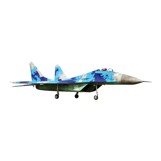
MIG-29
95% ALMOST READY TO FLY
ALL BALSA - PLY WOOD CONSTRUCTION
COVERED IN A HEAT-SHRINK FILM WITH PRINTED.
SPECIFICATION:
- Wingspan: 1,635 mm (64.4 in).
- Length: 2.260 mm(89.0 in)
- Weight: 12.4 kg (27 lbs).
- Wing area: 79.3 dm2
- Wing loading: 156.3 g/dm2.
- Wing type: Naca Airfoil.
- Servo mount: 37mm x 16mm
and 41mm x 21mm.
- Gear type: Electric Retract Gear
with oleo struts (included) and
controller box (included).
Instruction Manual Book
Item code: BH185
Parts listing required (not included):
- Radio: 8 channels minimum.
- Servo: 7 (HV high torque servos),
size: (35 x 15)mm, (2 HV high torque servos,
size 40mm x 20mm torque : 35-42kg/cm Elevator)
- Engine: Turbine Jet Engine with thrust 13kg
Recommended Battery set up (not included):
- Battery receiver:
2S- 7.4V 2,200mAh - 3,200mAh.
3S- 11.1V 2,200mAh - 3,200mAh.
Made in Vietnam.
Advertisement
Table of Contents

Subscribe to Our Youtube Channel
Related Manuals for Black Horse Model MIG-29


Summary of Contents for Black Horse Model MIG-29
- Page 1 Instruction Manual Book Item code: BH185 MIG-29 95% ALMOST READY TO FLY ALL BALSA - PLY WOOD CONSTRUCTION COVERED IN A HEAT-SHRINK FILM WITH PRINTED. SPECIFICATION: Parts listing required (not included): - Wingspan: 1,635 mm (64.4 in). - Radio: 8 channels minimum.
-
Page 2: Table Of Contents
Thank you for purchasing Black Horse Model products. With over 18 years experience in production and fly testing, Black Horse Model is committed to bring the best quality products and good service to customers. Along with a team of creative engineers and skilled workers, we will always accompany with customers by our great experiences, fully enthusiasm... -
Page 3: Warranty
In that Black Horse Model has no control over the final assembly or material used for final assembly, SUGGESTION Black Horse Model is not responsible for loss of use , or other incidental or consequential damages. To avoid scratching your new airplane, do not... -
Page 4: Covering Tools
MIG-29 Item code: BH185 Instruction Manual FLIGHT WARNINGS ADHESIVES AND REQUIRED TOOLS When ready to fly, first extend the transmitter aerial. Thin CA Switch on the transmitter. 30-minute epoxy Switch on the receiver. 6-minute epoxy Check that the wings are correctly fitted to the Threadlocker thread locking cement fuselage. - Page 5 MIG-29 Item code: BH185 Instruction Manual • Officially designated AMA Air Show Teams (AST) are authorized to use devices and practices as defined within the Team AMA Program Document. (AMA Document #718.) (j) Not operate a turbine-powered aircraft, unless in compliance with the AMA turbine regulations. (AMA Document #510-A.)
-
Page 6: Parts Listing (Not Included)
MIG-29 Item code: BH185 Instruction Manual PARTS LISTING (NOT INCLUDED). Servo extension leads....3pcs. 920mm ..8pcs. 620mm ..4pcs. Turbine Jet Engine with thrust 13 kg 220mm ..4pcs. LiPo: 3S- 11.1V - 3,200mAh....1 Packs Servos size: 40.3x 20.2mm Torque:7.4V 36 - 42 kg/cm... - Page 7 MIG-29 Item code: BH185 Instruction Manual Rudder spare part . Fuselage. 4: Rudder. 1a: fuselage nose set Landing Gear part 5: Anten Cockpit set Engine spare part. Fuel tank. Pipe Wing spare part CG spare part Pla�c fuselage Wing (2a(right wing);...
- Page 8 MIG-29 Item code: BH185 Instruction Manual 44mm Pinned Hinge Aileron 2.6x45mm Pushrod 3x16mm Button Head 3mm Lock Nut Plastic - - - 6 - - - 4 Cap Screw - - - 4 - - - 4 67mm Pinned Hinge Flap...
-
Page 9: Installing The Ailerons And Flaps
MIG-29 Item code: BH185 Instruction Manual INSTALLING THE AILERONS AND FLAPS Horn 44mm Pinned Hinge Aileron - - - 6 - - - 2 67mm Pinned Hinge Flap 6x50mm Aluminium - - - 6 - - - 4 Flap 67mm... -
Page 10: Installing The Aileron And Flap Servor
MIG-29 Item code: BH185 Instruction Manual INSTALLING THE AILERON AND FLAP SERVOS Ball Link 3mm Lock Nut 2.6x45mm Pushrod 3x12mm Button Head - - - 4 - - - 8 Cap Screw - - - 4 - - - 4... - Page 11 MIG-29 Item code: BH185 Instruction Manual Horn 2x10mm Tp Screw 3mm Lock Nut 2x10mm Tp Screw 3x12mm Button Head Cap Screw For Flap Servo 90⁰ 3x12mm Button Head Cap Screw 2.6x100mm Pushrod 3mm Flat Washer 3mm Lock Nut 3mm Lock Nut...
- Page 12 MIG-29 Item code: BH185 Instruction Manual 2x10mm Tp Screw 2x10mm Tp Screw Bottom view Flap Cable Aileron Cable Assemble left and right sides the same way.
-
Page 13: Installing The Fuselage
MIG-29 Item code: BH185 Instruction Manual INSTALLING THE FUSELAGE NOSE Fuselage nose 4x10mm Button Head Cap Screw - - - 2 4mm aluminum Washer - - - 1 - - - 2 Top view Top view 4mm aluminum Washer 4x10mm Button... -
Page 14: Installing The Main Landing Gear And Nose Gear
MIG-29 Item code: BH185 Instruction Manual INSTALLING THE MAIN LANDING GEAR AND NOSE GEAR 4x20mm Button Head Cap Screw 3mm Lock Nut Nose Gear Main Gear 3x12mm Button Head Cap Screw - - - 1 - - -12 Controller Box... - Page 15 MIG-29 Item code: BH185 Instruction Manual Bottom view 4x20mm Button Head Cap Screw 4x20mm Button Head Cap Screw 4mm Spring Washer 4mm Spring Washer 4x20mm Button Head 4mm Spring Washer Cap Screw Bottom view Plastic Apply epoxy glue.
-
Page 16: Installing The Horizontal Stabilizer Servo
MIG-29 Item code: BH185 Instruction Manual INSTALLING THE HORIZONTAL STABILIZER SERVO Ø12 x 190mm Aluminium Tube 2x10mm Tp Screw 3x15mm Button Head Cap Screw Ø20 x 9mm Collar Aluminium - - - 4 - - - 8 - - - 2... -
Page 17: Installing The Horizontal
MIG-29 Item code: BH185 Instruction Manual INSTALLING THE HORIZONTAL Ø20x2mm Flat Washer Aluminium Bottom view Collar Aluminium Assemble left and right Apply epoxy glue. sides the same way. - Page 18 MIG-29 Item code: BH185 Instruction Manual Bottom view 3x4mm Set Screw 3mm Flat Washer 3x15mm Button Head Cap Screw Lock Nut 120mm Pushrod 3mm Flat Washer The number of times Assemble left and right the same way Assembly sides the same way.
- Page 19 MIG-29 Item code: BH185 Instruction Manual 2x10mm Tp Screw Bottom view Bottom view Assemble left and right sides the same way.
-
Page 20: Installing The Vertical Stabilizer
MIG-29 Item code: BH185 Instruction Manual INSTALLING THE VERTICAL STABILIZER 44mm Pinned Hinge - - - 2 6x50mm Aluminium - - - 2 Rudder 44mm 6x50mm Aluminium Assemble left and right Apply threadlocker Cut off shaded portion Apply epoxy glue. -
Page 21: Installing The Vertical Stabilizer Servo
MIG-29 Item code: BH185 Instruction Manual INSTALLING THE VERTICAL STABILIZER SERVO 2.6x45mm Pushrod 3x12mm Button Head Cap Screw Horn - - - 2 - - - 2 Ball Link - - -2 3mm Flat Washer - - - 4 3x16mm Button Head... -
Page 22: Installing The Vertical Stabilizer To Fuselage
MIG-29 Item code: BH185 Instruction Manual Left view Lock Nut Ball link 3mm Flat Washer 2.6x 45mm Aluminium ball 3x12mm 3x16mm Button Head Button Head Cap Screw Cap Screw INSTALLING THE VERTICAL STABILIZER TO FUSELAGE Plastic Ø12x135mm Fiber Carbon Tubei... - Page 23 MIG-29 Item code: BH185 Instruction Manual Plastic Assemble left and right Apply epoxy glue. sides the same way.
- Page 24 MIG-29 Item code: BH185 Instruction Manual 3mm Hex wrench Assemble left and right sides the same way.
-
Page 25: Installing The Engine And Exhaust Pipe
MIG-29 Item code: BH185 Instruction Manual INSTALLING THE ENGINE AND EXHAUST PIPE Exhaust Tube 3x15mm TP Tapping Screw Pipe - - - 10 - - - 1 - - - 2 Exhaust Tube Engine 25mm Must be purchased The number of times Apply epoxy glue. - Page 26 MIG-29 Item code: BH185 Instruction Manual 3x15mm TP Tapping Screw 3x15mm TP Tapping Screw 1.5mm Drill holes using the stated. (in this case 1.5mm 1.5mm...
-
Page 27: Installing The Fuel Tank
MIG-29 Item code: BH185 Instruction Manual INSTALLING THE FUEL TANK Clunks Yak 3 alumminium Fiber glass - - - 2 - - - 2 - - - 2 - - - 2 - - - 4 - - - 2... - Page 28 MIG-29 Item code: BH185 Instruction Manual Magnetic Anodized Fuel Dot Top view Main Fuel Tank - - - - - 2 Alu. Anodized Fuel Vent Line Plug - - - - - 2 Fuel Dot Tygon Tubing Tank Vent Top view...
- Page 29 MIG-29 Item code: BH185 Instruction Manual FUEL SYSTEM To Turbine Fuel Main Fuel Tank Connection Safety Petcock Filter Vent Fuel Pump UAT Tank Fuel Supply Main Fuel Tank Top view 4x12mm Button Head Cap Screw 4mm aluminum Washer...
-
Page 30: Installing The Smoke Tank
MIG-29 Item code: BH185 Instruction Manual Top view INSTALLING THE SMOKE TANK Top view Tygon Tubing Smoke tank Must be purchased separately! -
Page 31: Installing The Wings To Fuselage
MIG-29 Item code: BH185 Instruction Manual SMOKE SYSTEM To Exhaust Tube Fuel Supply Vent to Battery to Receiver Smoke Tank Smoke Pump INSTALLING THE WINGS TO FUSELAGE Plastic Ø19 x 823mm Aluminium Tube Bottom view - - - 4 - - - 1... - Page 32 MIG-29 Item code: BH185 Instruction Manual Ø19x823mm Aluminium Tube Bottom view 3mm Hex wrench Bottom view The number of times Assemble left and right Apply epoxy glue. the same way Assembly sides the same way. (in this case twice).
-
Page 33: Installing The Receiver, Battery, Controller Box And Switch
MIG-29 Item code: BH185 Instruction Manual INSTALLING THE RECEIVER, BATTERY, CONTROLLER BOX AND SWITCH Top view Battery engine Smoke Pump Gear Box Battery 4x12mm Button Head Cap Screw 4mm aluminum Washer Top view... -
Page 34: Installing Cockpit Fuselage
MIG-29 Item code: BH185 Instruction Manual INSTALLING THE COCKPIT FUSELAGE Position the canopy so the rear frame on the Canopy Pilot Center Stick Cockpit Hatch canopy is aligned with the rear edge of the cockpit opening. Use canopy glue to secure - - - 1 the canopy to the canopy hatch. -
Page 35: Platic Fuselage
MIG-29 Item code: BH185 Instruction Manual Adhesive tape. PLATIC FUSELAGE Platic - - - 1 Platic The number of times Assemble left and right Apply epoxy glue. sides the same way. the same way Assembly (in this case twice). -
Page 36: Balancing
MIG-29 Item code: BH185 Instruction Manual LATERAL BALANCE BALANCING 1. It is critical that your airplane be balanced correctly. After you have balanced a plane on the C.G. Improper balance will cause your plane to lose You should laterally balance it. Doing this will control and crash. - Page 37 MIG-29 Item code: BH185 Instruction Manual Assemble left and right Cut off excess. Pay close attention here. sides the same way.
-
Page 38: Control Throws
MIG-29 Item code: BH185 Instruction Manual CONTROL THROWS FLIGHT PREPARATION PRE FLIGHT CHECK 1. We highly recommend setting up a plane using the control throws listed. 1. Completely charge your transmitter and receiver batteries before your first day of flying. -
Page 39: For Your Radio Installation Basic Connection For Airplane And Adjustment Of Servos
MIG-29 Item code: BH185 Instruction Manual... -
Page 40: Main Gear Dimensional Detail
MIG-29 Item code: BH185 Instruction Manual 120mm 73mm 34mm 19mm 30mm 72mm 30mm 47mm 107mm 52mm 16 mm... - Page 42 MIG-29 Item code: BH185 Instruction Manual I/C FLINGT WARNINGS Keep all onlookers (especially small Always operate in open areas, away children and animals) well back from factories, hospitals, schools, from the area of operation. This is NEVER buildings and houses etc. NEVER...
Need help?
Do you have a question about the MIG-29 and is the answer not in the manual?
Questions and answers