Table of Contents
Advertisement
Quick Links
Instruction Manual Book
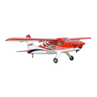
TURBO BEAVER
ALL BALSA - PLY WOOD CONSTRUCTION.
COVERED WITH ORACOVER
Glow and EP
95% ALMOST READY TO FLY
SPECIFICATION:
- Wingspan: 2,250 mm (88.58 in).
- Length: 1,675 mm ( 65.94 in).
- Weight: 5.5kg (12.1lbs).
- Wing area: 59.7 dm .
- Wing loading: 92.1g/dm .
- Wing type: USA 35-B Airfoil.
- Spinner: 70mm
- Servo mount: 42mm x 21mm.
- Gear type: Aluminium Hi-grade for main gear
and spring wire for tail gear (included).
2
2
Item code: BH162.
Parts listing required (not included):
- Radio: 06 channels.
- Servo: 08 servos.
-
- Engine: 25 - 35 cc gas. NGH GT25/GF30
reccomended
- Motor: Brushless outrunner 1800-2300W, 450KV.
- Propeller: Suit with your engine.
Recommended motor
and battery set up (not included):
- Motor: Admiral GP20 6320-295kV
- Lipo cell: 6-8 cells 4,000-5,500mAh.
- Receiver battery: 6V/ 1200mAh.
- ESC: 80 - 120A
Made in Vietnam.
Advertisement
Table of Contents

Subscribe to Our Youtube Channel
Related Manuals for Black Horse Model TURBO BEAVER BH162


Summary of Contents for Black Horse Model TURBO BEAVER BH162
- Page 1 Instruction Manual Book Item code: BH162. TURBO BEAVER ALL BALSA - PLY WOOD CONSTRUCTION. COVERED WITH ORACOVER Glow and EP 95% ALMOST READY TO FLY SPECIFICATION: - Wingspan: 2,250 mm (88.58 in). Parts listing required (not included): - Radio: 06 channels. - Length: 1,675 mm ( 65.94 in).
-
Page 2: Table Of Contents
Thank you for purchasing Black Horse Model products. With over 18 years experience in production and fly testing, Black Horse Model is committed to bring the best quality products and good service to customers. Along with a team of creative engineers and skilled workers, we will always accompany with customers by our great experiences, fully enthusiasm... -
Page 3: Warranty
In that Black Horse Model has no control over the final assembly or material used for final assembly, SUGGESTION Black Horse Model is not responsible for loss of use , or other incidental or consequential damages. To avoid scratching your new airplane, do not... -
Page 4: Covering Tools
TURBO BEAVER Item code: BH162 Instruction Manual FLIGHT WARNINGS ADHESIVES AND REQUIRED TOOLS When ready to fly, first extend the transmitter aerial. Thin CA Switch on the transmitter. 30-minute epoxy Switch on the receiver. 6-minute epoxy Check that the wings are correctly fitted to the Threadlocker thread locking cement fuselage. - Page 5 TURBO BEAVER Item code: BH162 Instruction Manual • Officially designated AMA Air Show Teams (AST) are authorized to use devices and practices as defined within the Team AMA Program Document. (AMA Document #718.) (j) Not operate a turbine-powered aircraft, unless in compliance with the AMA turbine regulations. (AMA Document #510-A.) 3.
-
Page 6: Parts Listing (Not Included)
TURBO BEAVER Item code: BH162 Instruction Manual PARTS LISTING (NOT INCLUDED). Servo extension leads....2 pcs. 420mm ..2 pcs. 190mm ..4 pcs. Engine: 20-30cc Gas. NGH GT25/GF30 recommended Propeller. Suit with your engine. LiPo. 6S - 22.2V- 4000-5000mAh. Motor: Admiral GP20 1 pcs. - Page 7 TURBO BEAVER Item code: BH162 Instruction Manual : Fuselage. : Wing panel (2a, 2b). : Horizontal stabilizer. : Rudder. : Aluminium wing dihedral brace. : Cowling. 2x10mm Screw - - - 6 : Cockpit fuselage (7a: Canopy, 7b : Pilot, 7c: Pilot seat , top hatch fuselage : Spinner.
-
Page 8: Preparation
TURBO BEAVER Item code: BH162 Instruction Manual PREPARATIONS: Use a covering iron with a covering sock on hign heat to tighten the covering if necessary. Apply pressure over sheeted areas to thoroughly bond the covering to the wood. INSTALLING THE AILERONS AND FLAPS Bottom view Flap Aileron... - Page 9 TURBO BEAVER Item code: BH162 Instruction Manual For Flap servo. For Aileron servo. Bottom view Flap Aileron Aileron and flap servos. approx.16mm 2x10mm Screw For Flap. For Flap. 1.5mm For Aileron. For Aileron. Screw 1.5mm 1.5mm For Aileron. 2x10mm Tp Screw Warning! - - - - 16 2x10mm...
-
Page 10: Installing The Control Horns And Linkages
TURBO BEAVER Item code: BH162 Instruction Manual INSTALLING THE CONTROL HORNS AND LINKAGES Nylon Clevis - - - 4 100mm Push rod - - 4 Horn Flaslink - - - - - - 4 Horn - - - - - - 4 1.7x8mm Cap Screw - - - - - - - 4 Bottom view... - Page 11 TURBO BEAVER Item code: BH162 Instruction Manual Pushrod Nylon Clevis Horn Servo arm Push rod Flaslink 1.7x8mm Cap Screw Mark the spot to attach Bend 90 Bottom view...
-
Page 12: Installing The Fuselage Servos
TURBO BEAVER Item code: BH162 Instruction Manual INSTALLING THE FUSELAGE SERVOS 1) Install the rubber grommets and brass collets into the elevator, rudder and throttle servos. Test fit the servos into the servo tray. Trim the tray if necessary to fit your servos. 2) Mount the servo to the tray using the mounting screws provided with your radio system. -
Page 13: Installing Horizontal Stabilizer
TURBO BEAVER Item code: BH162 Instruction Manual INSTALLING HORIZONTAL STABILIZER 1) Using a modeling knife, carefully remove the film 6) With the horizontal stabilizer correctly aligned. covering from the tail slots at the rear of the fuselage. Apply a thin CA layer to the top and bottom of the Make sure that you do not remove any wood from the stabilizer in the fuselage. -
Page 14: Installing The Control Horns And Linkages
TURBO BEAVER Item code: BH162 Instruction Manual INSTALLING THE CONTROL HORNS AND LINKAGES Nylon Clevis Horn Pushrod Nylon Clevis - - - - 2 2.2mm 800mm Push rod - - 2 Flaslink - - - - - - 2 Horn Horn - - - - - - 2 1.7x8mm Cap Screw... -
Page 15: Installing The Tail Gear
TURBO BEAVER Item code: BH162 Instruction Manual INSTALLING THE TAIL GEAR 35mm 3mm Wheel Colar Fuselage Bottom side - - - - - - 2 3x15mm Tp Screw - - - - - 2 3x15mm Tp Screw Secure 3mm Wheel Colar 2.5mm Cut off shaded portion carefully. - Page 16 TURBO BEAVER Item code: BH162 Instruction Manual Fuselage top side Control horns and linkages for rudder are install the same way as the aileron before (see page 14). Silicone Tube Horn Apply epoxy glue. Rudder pushrod Apply instant glue (C.A glue, super glue). Ensure smooth, non-binding movement when assembling.
-
Page 17: Installing Main Gear
TURBO BEAVER Item code: BH162 Instruction Manual INSTALLING MAIN GEAR 4x20mm Cap Screw 5mm Wheel Collar - - - - - - - 4 - - - - - - - 2 5x45mm Socket Head 5mm Flat washer Cap Screw - - - - - - - 4 - - - - - 2 4mm Spring Washer... - Page 18 TURBO BEAVER Item code: BH162 Instruction Manual BOTTOM VIEW 5mm Hex Nut 5mm Wheel Collar 5mm Flat washer 5mm Flat washer 5x45mm Socket Head Cap Screw...
-
Page 19: Installing The Wing Struts Set
TURBO BEAVER Item code: BH162 Instruction Manual WING STRUT SET 3x12mm Cap Screw - - - 2 4x15mm Cap Screw 3x6mm Button Head - - - - - - 4 Cap Screw - - - - - - 4 - - - 2 - - - - - - - - 8 3mm Spring Washer 4mm Flat Washer... -
Page 20: Installing The Wing To The Fuselage
TURBO BEAVER Item code: BH162 Instruction Manual 3x12mm TP Screw 3x12mm TP Screw Bottom view Assemble left and right sides the same way. INSTALLING THE WING TO THE FUSELAGE *** Test fit the aluminium tube dihedral brace into each wing 19x680mm Aluminium tube. - Page 21 TURBO BEAVER Item code: BH162 Instruction Manual 4x15mm Cap screw Attach the wings to the joiner tube and secure the wing panels to the fuselage. Main wing must be inserted and attached completely before fixing with screw. 4x15mm Cap screw for main wing fixture.
-
Page 22: Installing The Engine
TURBO BEAVER Item code: BH162 Instruction Manual INSTALLING THE ENGINE May be you also need to trim some wood from the tri-angle Using plate of plywood (supplied with the kit) mark the holes wood for the installation is easy. onto the fire wall for installing the engine mount for SIZE - 120 or DLE - 20CC , O.S - 22CC. - Page 23 TURBO BEAVER Item code: BH162 Instruction Manual 4mm Hex Nut 500mm Pushrod wire - - - 2 - - - - - - - 4 Size: 120 M4 Blind Nut 4x25mm Cap Screw - - 4 - - - - - 8 4mm Flat washer - - - - - - - 8 4mm Spring Washer...
- Page 24 TURBO BEAVER Item code: BH162 Instruction Manual TOP VIEW Electric Power TOP VIEW Apply threadlocker (screw cement).
-
Page 25: Installing The Stopper
TURBO BEAVER Item code: BH162 Instruction Manual INSTALLING THE STOPPER Cut off shaded portion... -
Page 26: Installing The Fuel Tank
TURBO BEAVER Item code: BH162 Instruction Manual INSTALLING THE FUEL TANK 5. When satisfied with the alignment of the stopper assembly tighten the 3mm x 20mm machine screw until the rubber stopper expands and 1. Using a modeling knife, cut one length of silicon seals the tank opening. -
Page 27: Installing The Throttle
TURBO BEAVER Item code: BH162 Instruction Manual INSTALLING THE THROTTLE Connector - - - - 1 1) Install one adjustable metal connector through reverse the direction of the servo, using the the third hole out from the center of one servo arm, transmitter. -
Page 28: Mounting The Cowl
TURBO BEAVER Item code: BH162 Instruction Manual MOUNTING THE COWL Enlarging the holes through the cowl will 1) Remove the muf f ler and needle valve assembly prevent the fiberglass from splitting when the from the engine. Slide the fiberglass cowl over the mounting screws are installed. - Page 29 TURBO BEAVER Item code: BH162 Instruction Manual TOP VIEW 3x12mm Tp Screw TOP VIEW Drill holes using the stated. (in this case 2mm...
-
Page 30: Installing The Switch, Receiver And Battery
TURBO BEAVER Item code: BH162 Instruction Manual INSTALLING THE SWITCH, RECEIVER AND BATTERY INSTALLING THE SWITCH 1) Plug the servo leads and the switch lead into the receiver. You may want to plug an aileron extension 1) The switch should be mounted on the fuselage into the receiver to make plugging in the aileron servo side, opposite the muffler, close enough to the lead easier when you are installing the wing. - Page 31 TURBO BEAVER Item code: BH162 Instruction Manual 4mm Spring Washer 10x15mm Plastic M4 Blind Nut 4mm Flat Washer 4x30mm Socket Head Cap Screw TOP VIEW 10x50mm Plastic 4mm Spring Washer 4mm Flat Washer 4x70mm Socket Head Cap Screw 4mm Flat Washer...
-
Page 32: Installing Cockpit Fuselage
TURBO BEAVER Item code: BH162 Instruction Manual TOP VIEW INSTALLING COCKPIT FUSELAGE 2x10mm Tp Screw - - - 6 TOP VIEW Open/Close... - Page 33 TURBO BEAVER Item code: BH162 Instruction Manual TOP VIEW TOP VIEW...
- Page 34 TURBO BEAVER Item code: BH162 Instruction Manual TOP VIEW Open/Close TOP VIEW 2x10mm Tp Screw...
-
Page 35: Installing The Spinner, Propeller
TURBO BEAVER Item code: BH162 Instruction Manual INSTALLING THE SPINNER, PROPELLER * Install the spinner back-plate, propeller and spinner Warning! cone. The spinner cone is held in place using two screws. The propeller should not touch any part of the spinner cone. - Page 36 TURBO BEAVER Item code: BH162 Instruction Manual...
-
Page 37: Balancing
TURBO BEAVER Item code: BH162 Instruction Manual BALANCING 2) If one side of the wing fall, that side is heavier than the opposite. Add small amounts of lead weight to the bottom side of the lighter wing half's It is critical that your airplane be balanced wing tip. -
Page 38: For Your Radio Installation Basic Connection For Airplane And Adjustment Of Servos
TURBO BEAVER Item code: BH162 Instruction Manual FOR YOUR RADIO INSTALLATION BASIC CONNECTION FOR AIRPLANE AND ADJUSTMENT OF SERVOS Example of connection For more information, refer to radio system instruction manual. Follow instruction manual of Engine and Battery. Aileron Servo Aileron Aileron Servo Aileron... -
Page 39: Main Gear Dimensional Detail
TURBO BEAVER Item code: BH162 Instruction Manual MAIN GEAR DIMENSIONAL DETAIL 34mm 100mm 66mm 3.5mm 5.1mm hold 35mm 5.1mm hold 177mm TAIL GEAR DIMENSIONAL DETAIL 53mm 28mm 1.5mm hold 2.5mm hold 35mm... -
Page 40: Decoration
TURBO BEAVER Item code: BH162 Instruction Manual DECORATION < Top view > < Bottom view > < Side view > Left < Side view > Right ORACCOVER #21-023 - Ferrari Red #21-010 - White #21-071 - Black... -
Page 42: I/C Flying Warning
I/C FLYING WARNINGS Always operate in open areas, away from NEVER fly near power lines,aerials or ALWAYS adjust the engine from behind factories, hospitals, schools, buildings the propeller, and do not allow any part of other dangerous areas including airports, and houses etc. -
Page 43: I/C Flying Guide
I/C FLYING GUIDELINES Operate the control sticks on the ALWAYS land the model INTO When ready to fly, first extend transmitter and check that the the wind, this ensures that the the transmitter aerial. control surfaces move freely and in model lands at the slowest possible the CORRECT directions.
Need help?
Do you have a question about the TURBO BEAVER BH162 and is the answer not in the manual?
Questions and answers