Table of Contents
Advertisement
Quick Links
SPECIFICATION
Wingspan :
Length
Weight
Radio
Servo
Engine
Parts listing required(not included)
Electric Motor: EMAX 2826/06.
Battery: 4 Cells-Li-Poly-14.8V- 4,000 mAh-20 c .
Speed Control: 60A
Instruction Manual book
1,780mm
:
1,320mm
:
2.65kg
:
04 channels.
:
04 -05 servos.
:
46
2 stroke
52
4 stroke
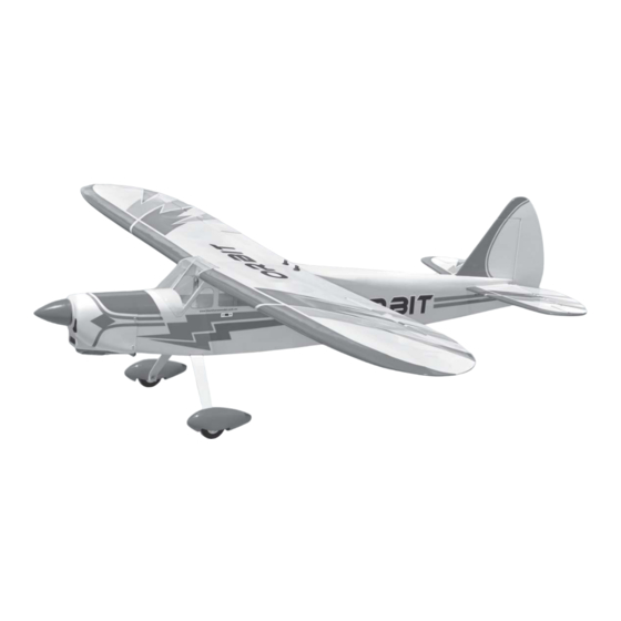
ITEM CODE: BH 106
70.08 in.
51.97 in.
5.83 Lbs.
Made in Vietnam.
Advertisement
Table of Contents

Related Manuals for Black Horse Model ORBIT BH106


Summary of Contents for Black Horse Model ORBIT BH106
- Page 1 Instruction Manual book ITEM CODE: BH 106 SPECIFICATION Wingspan : 1,780mm 70.08 in. Length 1,320mm 51.97 in. Weight 2.65kg 5.83 Lbs. Radio 04 channels.
-
Page 2: Parts List
Instruction Manual ORBIT- ITEM CODE BH106 This instruction manual is designed to help you build a great flying aeroplane. Please read this manual thoroughly before starting assembly of your ORBIT Use the parts listing below to identify all parts. WARNING Please be aware that this aeroplane is not a toy and if assembled or used incorrectly it is capable of causing injury to people or property. -
Page 3: Safety Precaution
Instruction Manual ORBIT- ITEM CODE BH106 Caution: this model is not a toy! If you are a beginner to this type of powered model, please ask an experienced model flyer for help and support. If you attempt to operate the model without knowing what you are doing you could easily injure yourself or somebody else. - Page 4 Instruction Manual ORBIT- ITEM CODE BH106 REPLACEMENT SMALL PARTS 1. Aluminium landing gear. INSTALLING THE AILERON SERVOS. 2. Wheel pants. 1. Install the rubber grommets and brass eyelets onto the aileron servo. 3. Spinner. 4. Fuel tank. 5. Plastic parts for rudder and elevator pushrod.
- Page 5 Instruction Manual ORBIT- ITEM CODE BH106 2. Using a modeling knife, remove the cov- ering servo tray. R e m o v e covering C/A glue Servo tray. C/A glue Secure 3. Drill 1,5mm pilot holes through the block of wood for each of the four mounting screws provided with the servo.
-
Page 6: Installing The Aileron Linkages
Instruction Manual ORBIT- ITEM CODE BH106 Secure. INSTALLING THE AILERON LINKAGES. Installing the aileron linkages as pictures below. 2x10mm. M2 M2 lock nut 80 mm. Aileron pushrod. Secure Aileron pushrod. INSTALLING THE AILERON CONTROL HORN. 2mm X 20mm. 1) Insert aileron control horn to the aileron. Repeat the procedure for the other wing half. -
Page 7: Installing The Engine Mount
Instruction Manual ORBIT- ITEM CODE BH106 C/A glue. Epoxy glue. Epoxy glue. THERE ARE TWO OPTIONS: 1. ENGINE MOUNT. 2. ELECTRIC MOTOR INSTALLING THE ENGINE MOUNT. OPTION 1: ENGINE MOUNT. 3 x 20mm C/A glue. -
Page 8: Installing The Stopper Assembly
Instruction Manual ORBIT- ITEM CODE BH106 FUEL TANK. INSTALLING THE STOPPER ASSEMBLY 5. Test fit the stopper assembly into the Fuel pick- up tube Vent tube tank. It may be necessary to remove some of the flashing around the tank opening using a modeling knife. -
Page 9: Installing The Engine
Instruction Manual ORBIT- ITEM CODE BH106 Blow through one of the lines to ensure the fuel lines have not become kinked inside the fuel tank compartment. Air should flow through easily. 9. To secure the fuel tank in place, apply a bead of silicon sealer to the forward area of the tank, where it exits the fuselage behind the engine mounting box and to the rear of the tank... - Page 10 Instruction Manual ORBIT- ITEM CODE BH106 Drill a hole 4mm diameter Secure R e m o v e covering Pushrod wire Plastic part for bottom Engine . P u s h r o d wire R e m o v e covering Secure...
- Page 11 Instruction Manual ORBIT- ITEM CODE BH106 Drill a hole 3mm diameter C/A glue. Right side Secure Left side Drill a hole 3mm diameter. Secure 3 x 15 mm...
- Page 12 Instruction Manual ORBIT- ITEM CODE BH106 COWLING. Right side 1. Slide the fiberglass cowl over the en- gine and line up the back edge of the cowl with the marks you made on the fuselage. Trim and cut Mark line Bottom side ...
-
Page 13: Installing The Spinner
Instruction Manual ORBIT- ITEM CODE BH106 Mark line Front view INSTALLING THE SPINNER. 3 x 12mm 3mm x 12mm Mark line Install the spinner backplate, propeller and spinner cone. The spinner cone is held in place using two 3mm x 15mm wood screws. Secure Secure Secure... - Page 14 Instruction Manual ORBIT- ITEM CODE BH106 INSTALLING ELECTRIC MOTOR. INSTALLING THE THROTTLE PUSHROD. 1. Install one adjustable metal connector OPTION 2: ELECTRIC MOTOR. through the third hole out from the center of one servo arm, enlarge the hole in the servo arm using a 2mm drill bit to accommodate the servo connector.
- Page 15 Instruction Manual ORBIT- ITEM CODE BH106 Right side 4 x 60 mm aluminium tube Left side 230 mm Battery tray. 3 x 10mm Cut. C/A glue C/A glue Secure...
-
Page 16: Horizontal Stabilizer
Instruction Manual ORBIT- ITEM CODE BH106 Battery. Front view ELEVATOR INSTALLATION. SERVO INSTALLATION. 1. Install the rubber grommets and brass collets into the elevator servo. Test fit the servo into the servo tray. 2. Mount the servo to the tray using the ... - Page 17 Instruction Manual ORBIT- ITEM CODE BH106 C/A glue C/A glue Bottom side C/A glue 2 Using a modeling knife, cut away the covering from the fuselage for the stabilizer and remove it. 3. Mark the shape of the vertical on the left and right sides onto the horizontal stabilizer C/A glue using a left-tip pen.
- Page 18 Instruction Manual ORBIT- ITEM CODE BH106 Remove covering Epoxy glue 6. After the epoxy has fully cured, remov the masking tape or T-pins used to hold the stabilizer in place and carefully inspect the glue joints. Use more epoxy to fill in any gaps that were not filled previously and clean up the excess using a paper towel and rubbing alcohol.
-
Page 19: Elevator Pushrod Installation
Instruction Manual ORBIT- ITEM CODE BH106 C/A glue C/A glue Secure. Top side ELEVATOR PUSHROD INSTALLATION. Elevator pushrod install as same as the way of aileron pushrod. M2 lock nut. ELEVATOR CONTROL HORN INSTALLA- TION. Elevator control horn install as same as the way of aileron control horn. -
Page 20: Vertical Installation
Instruction Manual ORBIT- ITEM CODE BH106 VERTICAL INSTALLATION. C/A glue Elevator pushrod Elevator pushrod Rudder pushrod. Bottom side Hinge. C/A glue... - Page 21 Instruction Manual ORBIT- ITEM CODE BH106 2. Put the rudder into the fuselage as same as picture below. C/A glue Hinge slot. 3. Mark the shape of the vertical on the left and right side of the rudder on to the hori- zontal stabilizer using a felt-tip pen.
-
Page 22: Rudder Control Horn Installa- Tion
Instruction Manual ORBIT- ITEM CODE BH106 Vertical Stabilizer. Horizontal 90º Stabilizer. C/A glue 5. Put the vertical stabilizer back in place. Using a triangle, check to ensure that the vertical stabilizer is aligned 90 de- gree to the horizontal stabilizer. Top side Epoxy glue RUDDER CONTROL HORN INSTALLA-... -
Page 23: Rudder Pushrod Installation
Instruction Manual ORBIT- ITEM CODE BH106 E l e v a t o r E l e v a t o r pushrod pushrod R u d d e r pushrod Secure RUDDER PUSHROD INSTALLATION. Rudder pushrod install as same as the way of aileron pushrod. -
Page 24: Mounting The Tail Wheel Bracket
Instruction Manual ORBIT- ITEM CODE BH106 Secure Repeat the process for the other wheel. MOUNTING THE TAIL WHEEL BRACKET. 1. Set the tail wheel assembly in place on the plywood plate. The pivot point of the tail wheel wire should be even with the rud- der hinge line and the tail wheel bracket should be centered on the plywood plate. -
Page 25: Installing The Switch
Instruction Manual ORBIT- ITEM CODE BH106 Switch 3. Secure the tail wheel bracket in place INSTALLING THE RECEIVER AND BATTERY. using three 3mm x 12mm wood screws. Be careful not to overtighten the screws. ... - Page 26 Instruction Manual ORBIT- ITEM CODE BH106 Receiver BALANCING. WING ATTACHMENT. 1) It is critical that your airplane be bal- See picture wing attach to fuselage. anced correctly. Improper balance will cause your plane to lose control and crash. THE CENTER OF GRAVITY IS LOCATED 65MM BACK FROM THE LEADING EDGE OF THE WING.
-
Page 27: Pre-Flight Check
Instruction Manual ORBIT- ITEM CODE BH106 *If possible, first attempt to balance the model PRE-FLIGHT CHECK. by changing the position of the receiver bat- tery and receiver. If you are unable to obtain 1) Completely charge your transmitter and good balance by doing so, then it will be nec- receiver batteries before your first day of fly- essary to add weight to the nose or tail to...
Need help?
Do you have a question about the ORBIT BH106 and is the answer not in the manual?
Questions and answers