Table of Contents
Advertisement
Quick Links
Advertisement
Table of Contents

Subscribe to Our Youtube Channel
Related Manuals for SMAR LD400WH


Summary of Contents for SMAR LD400WH
- Page 3 Smar provides specific training to instruct and qualify such professionals. However, each country must comply with the local safety procedures,...
-
Page 4: Table Of Contents
Table of Contents TABLE OF CONTENTS INTRODUCTION ............................VII TRANSMITTER GENERAL VIEW ......................XIII INSTALLATION FLOWCHART ........................ XV SECTION 1 - INSTALLATION ........................1.1 GENERAL................................... 1.1 MOUNTING ................................1.1 ELECTRONIC HOUSING ............................1.12 WIRING ..................................1.13 INSTALLATION IN HAZARDOUS LOCATIONS ...................... 1.14 INTRINSICALLY SAFE ............................ - Page 5 Visão Geral do Transmissor...
-
Page 6: Introduction
Introduction INTRODUCTION WirelessHART technology overview The WirelessHART technology is based on a wireless mesh network communication protocol used in process automation applications. It adds wireless capabilities to the HART protocol, while maintaining compatibility with existing HART devices, commands and already known and used tools. - Page 7 Introduction the network that requested services to it, as well as manages the routes between the devices on the mesh network. Specifically, about the joining process of a WirelessHART device to the network, the Network Manager validates the Network ID and the Join Key attributes which are configured in the WirelessHART Gateway and WirelessHART devices.
- Page 8 – Operation, Maintenance, and Instruction Manual LD400 WirelessHART Scope definition Clearly define the scope of the network. Answer the question: why do we need the wireless network? To monitor process variables or to implement a non-critical control? The answer to this question will facilitate the understanding between the team members responsible for the network and determine one or more process units in the plant.
- Page 9 Introduction o Place the repeaters as needed. Smar offers the RP400WH, the best cost-benefit on the market. Installation As mentioned before, WirelessHART devices should be connected to the process and configured the same way as conventional wired HART devices. Handheld terminals can be used normally. Just be sure of having it properly uploaded with the latest DD files of the devices.
- Page 10 Always install the equipment with the antenna in the vertical direction. If the equipment is installed horizontally, consult Smar to purchase the antenna for horizontal mounts, so that it is 90° with the equipment. No Wireless equipment should be located at the highest point of the plant, preventing it from working as a possible lightning rod;...
- Page 11 (when available). When changing the Battery Module (code Smar 400-1209) the replacement must be configured through a configurator that will reset the counting of the estimated lifetime for the new module. ATTENTION: do not dispose of the Battery Module in common garbage.
- Page 12 – Operation, Maintenance, and Instruction Manual LD400 WirelessHART Gateway commissioning a) Make sure that the gateway is available to the host system; b) Check the gateway and make sure it has at least five devices directly connected to it; c) Check if 25 % of the devices are connected directly to the gateway. If necessary, add repeaters; The gateway connects the devices to the host system.
-
Page 13: Transmitter General View
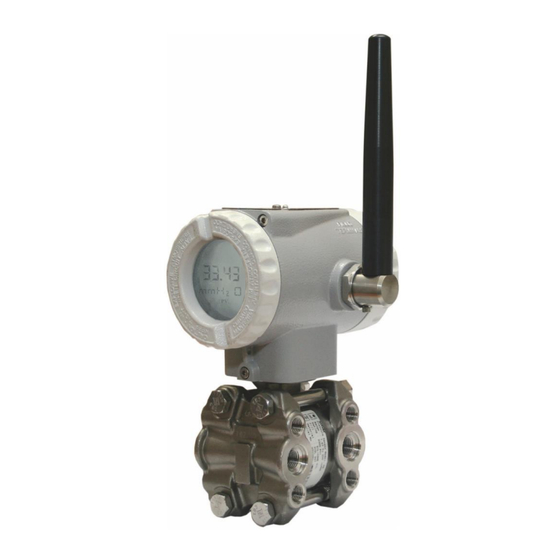
The process variable, as well as the diagnostic monitoring and information, are supplied by the digital communication protocol. The LD400 is available in the WirelessHART communication protocol. Read carefully these instructions for better use of the LD400 WirelessHART . Smar pressure transmitters are protected by American patents n. 6,433,791 and 6,621,443. XIII... - Page 14 – Operation, Maintenance, and Instruction Manual LD400 WirelessHART...
-
Page 15: Installation Flowchart
Installation Flowchart Installation Flowchart Start Was the transmitter Check area classification configured on the bench and their practices and to match the application? if the transmitter can be powered therein. Install the transmitter preferably Configure the transmitter on weather- protected areas. (Section 1 and 4) Configure the measuring range Install it on the field following the... - Page 16 – Operation, Maintenance, and Instruction Manual LD400 WirelessHART...
-
Page 17: Section 1 - Installation
Section 1 INSTALLATION General NOTE The installation carried out in hazardous areas should follow the recommendations of the IEC60079-14 standard. The overall accuracy of a flow, level, or pressure measurement depends on several variables. Although the transmitter has an outstanding performance, proper installation is essential to maximize its efficiency. - Page 18 – LD400 WirelessHART Operation and Maintenance Instruction Manual Figure 1.1 (a) – Dimensional Drawing and Mounting Position for the LD400 WirelessHART – Differential Pressure, Flow, Gage, Absolute and High Static Pressure Transmitter with Mounting Bracket...
- Page 19 Installation Figure 1.1 (b) – Dimensional Drawing and Mounting Position for the LD400 WirelessHART – Flanged Pressure Transmitter (Integral Flange)
- Page 20 – LD400 WirelessHART Operation and Maintenance Instruction Manual Figure 1.1 (c) – Dimensional Drawing and Mounting Position for the LD400 WirelessHART – Flanged Pressure Transmitter with Housing...
- Page 21 Installation Figure 1.1 (d) – Dimensional Drawing and Mounting Position for the LD400 WirelessHART – Sanitary Transmitter with Extension...
- Page 22 – LD400 WirelessHART Operation and Maintenance Instruction Manual Figure 1.1 (e) – Dimensional Drawing and Mounting Position for the LD400 WirelessHART – Sanitary Transmitter without Extension...
- Page 23 Installation Figure 1.1 (f) – Dimensional Drawing and Mounting Position for the LD400 WirelessHART – Gage Inline Pressure Transmitter...
- Page 24 – LD400 WirelessHART Operation and Maintenance Instruction Manual Figure 1.1 (g) – Dimensional Drawing and Mounting Position for the LD400 WirelessHART – Pressure Transmitter with Extended Probe...
- Page 25 Installation minimum 0.5 m minimum 1.5 m Notes: 1- Vertical obstacle 2- Floor 3- Minimum 3 equipment neighbors 4- Recommended 5 equipment neighbors Figure 1.2 – Wiring for Wireless Transmitter...
- Page 26 – LD400 WirelessHART Operation and Maintenance Instruction Manual MOUNTING ON THE PANEL OR WALL (See Section 6 –spare parts for mounting brackets available) Figure 1.3 – Drawing of LD400 WirelessHART Mounted on the Panel or Wall Some examples of installation, illustrating the transmitter position in relation to the taps, are shown in Figure 1.3.
- Page 27 Installation Figure 1.4 – Position of the Transmitter and Taps When the sensor is in the horizontal position, the fluid weight pushes the diaphragm down and then the lower pressure trim must be applied. See Figure 1.5. DIAPHRAGM SENSOR HEAD OF THE FLUID DIAPHRAGM SENSOR SENSOR IN THE VERTICAL POSITION SENSOR IN THE HORIZONTAL POSITION...
-
Page 28: Electronic Housing
– LD400 WirelessHART Operation and Maintenance Instruction Manual Electronic Housing The electronic housing can be rotated to adjust the digital display on a better position. To rotate it, loose the Housing Rotation Set Screw, see Figure 1.6. Figure 1.6 – Cover Locking and Housing Rotating Set Screw NOTES LD400 WirelessHART must always be installed on the antenn positioned upward. -
Page 29: Wiring
Installation Figure 1.7 – External Ground Screw Wiring The equipment comes from the factory with the Battery Module turned off, for safety reasons and shipping regulations. To turn it on using the front switch, it is necessary to previously connect the Battery Module connector to the main board, terminal “CN3”. -
Page 30: Installation In Hazardous Locations
The instrument modification or parts replacement supplied by other than authorized representative of Smar is prohibited and will void the certification. The transmitters are marked with options of the protection type. The certification is valid only when the protection type is indicated by the user. -
Page 31: Functional Description
Section 2 FUNCTIONAL DESCRIPTION Functional Description – Sensor The LD400 WirelessHART Smart Pressure Transmitters use capacitive sensors (capacitive cells) as pressure sensing elements, as shown in Figure 2.1 Figure 2.1 – Capacitive Cell Where: and P are the pressures in chambers H and L. CH = capacitance between the fixed plate on P side and the sensing diaphragm. - Page 32 – Operation and Maintenance Instruction Manual LD400 WirelessHART However, should the differential pressure (ΔP) apply to the capacitive cell not deflect the sensing diaphragm beyond d/4, it is possible to assume ΔP as proportional to Δd: By developing the expression: −...
- Page 33 Each battery has 2.5 grams of lithium, totaling 5.0 grams Battery Module. WARNING By no means should be used other than the power supplied by batteries Module Smar (code 400- 1209). When you replace the Battery Module (code Smar 400-1209) to set up the replacement via a configurator that will cause the device to reboot count the estimated lifespan for the new module.
-
Page 34: Functional Description - Ld400 Wirelesshart
– Operation and Maintenance Instruction Manual LD400 WirelessHART Figure 2.3 – Local Adjustment Functional Description – LD400 WirelessHART Software Refer to the block diagram Figure 2.4. The function of each block is described below. ENGINEERING PRESSURE UNIT CALIBRATION LRV & URV FUNCTION LINEAR, SQUARED, TABLE ON/OFF... -
Page 35: Functional Description - Display (Lcd)
Functional Description Engineering The pressure value normalized it is converted for the engineering unit, considering the unit of selected pressure and the Upper Range Limit (URL). Calibration The pressure value is calculated in percents taking in consideration the work range provided by the Lower Range Value (LRV) and the Upper Range Value (URV). - Page 36 – Operation and Maintenance Instruction Manual LD400 WirelessHART Figure 2.6 – Display for LD400 WirelessHART Monitoring During normal operation, the LD400 WirelessHART is in the monitoring mode. In this mode, indication alternates between the three variables (LCD_1, LCD_2, LCD_3) as configured by the user.
- Page 37 - Battery Life: Burst mode to 8s, @25 ºC, network with at least 3 neighbor devices: 4 years Notes: Power Supply The batteries module used in the transmitters must be provided exclusively by Smar (PACK BATTERY - Code 400- 1209) and must be replaced in full when necessary. For specific battery composition details see Appendix B.
- Page 38 – Operation and Maintenance Instruction Manual LD400 WirelessHART Functional Specifications WARNING It is described here only the maximum pressures of some materials referenced in each standard, other materials on request. Temperatures above 150 ° C are not available in standard models. PRESSURES TABLE FOR SEAL AND LEVEL FLANGES DIN EN 1092-1 2008 STANDARD Maximum Temperature Allowed Pressure...
- Page 39 Technical Characteristics Functional Specifications Maximum Temperature Allowed Material Pressure -29 a Group Class Maximum Pressure Allowed (bar) 15.9 15.3 13.3 11.2 10.5 41.4 34.8 31.4 29.2 27.5 26.1 25.5 25.1 AISI316L 82.7 69.6 62.8 58.3 54.9 52.1 50.1 1500 206.8 200.1 173.9 145.8...
- Page 40 – Operation and Maintenance Instruction Manual LD400 WirelessHART Performance Specifications Span starting at zero, temperature of 25°C (77°F), atmospheric pressure, power supply of 24 Vcc, silicone or Reference Conditions halocarbon oil fill fluid, isolating diaphragms in 316L SST and digital trim equal to lower and upper range values. Standard Class: For range 0 and gage or differential model: 0.16 URL ≤...
- Page 41 Technical Characteristics For range 5 and gage model or high static pressure model: 0.16 URL ≤ span ≤ URL: ± 0.055 % do span 0.025 URL ≤ span < 0.16 URL: ± [0.0263 + 0.004688 URL/span] % span 0.00833 URL ≤ span < 0.025 URL: ± [0,00466 + 0,005214 URL/span] % span Accuracy (Continuation) For range 6 and gage model: 0.16 URL ≤...
- Page 42 – Operation and Maintenance Instruction Manual LD400 WirelessHART Physical Specifications Isolating Diaphragms: 316L SST, Hastelloy C276, Monel 400 or Tantalum Drain/Vent Valves and Plug: 316 SST, Hastelloy C276 or Monel 400 Flanges: Plated Carbon Steel, 316 SST (ASTM - A351 CF8M), Hastelloy C276 (ASTM - A494 CW-12MW) or Monel 400 O-Rings (For Flanges and Adapters): Buna-N, Viton™...
- Page 43 Technical Characteristics Humam Machine Interface Specifications Item Ícon Definition Indication of Primary Variable Blinking when the transmitter is seeking wireless network Blinking when the transmitter is connected to Indication of the State wireless network in the Display Operational transmitter in the wireless network Failed to connect to the wireless.
-
Page 44: Ordering Code
– Operation and Maintenance Instruction Manual LD400 WirelessHART Ordering Code MODEL DIFFERENTIAL PRESSURE, FLOW, GAGE, ABSOLUTE AND HIGH STATIC PRESSURE TRANSMITTER LD400 Smart Pressure Transmitter RANGE LIMITS Turn Down Tipo Unit Min. Max. Unit Máx. Min. Max. Differential (23) mbar Differential and Flow mbar Differential and Flow... - Page 45 Technical Characteristics LD400-D210-W0-IBD11 DIFFERENTIAL PRESSURE, FLOW, GAGE, ABSOLUTE AND HIGH STATIC PRESSURE TRANSMITTER (CONTINUATION) Flanges Bolts and Nuts Material 316 SST Carbon Steel (ASTM A193 B7M) (1) (20) Hastelloy C276 Super Duplex 316 SST according to NACE MR0175 / MR0103 (1a) Flange thread for fixing accessories (adapters, manifolds, mounting brackets, etc) 7/16 UNF M10 X 1.5...
- Page 46 – Operation and Maintenance Instruction Manual LD400 WirelessHART MODEL FLANGED PRESSURE TRANSMITTER LD400L Smart Pressure Transmitter RANGE LIMIT Turn Down TYPE Min. Max. Unit. Min. Max. Unit. Max. Level -500 mbar Note: The range can be extended up to 0.75 LRL and 1.2 URL with Level -250 -2500...
- Page 47 Technical Characteristics LD400-L210-W0-PBD00-I0 FLANGED PRESSURE TRANSMITTER (CONTINUATION) COD. Process Connection (High Side) 1" 150 # (ANSI B16.5) (28) 1" 300 # (ANSI B16.5) (28) 1" 600 # (ANSI B16.5) (28) 1 1/2" 150 # (ANSI B16.5) 1 1/2" 300 # (ANSI B16.5) 1 1/2"...
- Page 48 (10) Degrease cleaning not available for carbon steel flanges. LD400 IP66/68W IP66/68W Type4X/6P (11) Only available for ASME B16.5 flange. (12) Don´t available for JIS 2202 flange. (13) For this option consult Smar. (14) Don´t available for aluminum housing. (15) Efective for hydrogen migration processes. 3.12...
- Page 49 Technical Characteristics MODEL0 SANITARY PRESSURE TRANSMITTER LD400S Smart Pressure Transmitter RANGE LIMIT Turn Down TYPE Min. Max. Unit Min. Max. Unit Max. Sanitary -500 mbar Note: The range can be extended up to 0.75 LRL and 1.2 URL with Sanitary -250 -2500 2500...
- Page 50 – Operation and Maintenance Instruction Manual LD400 WirelessHART LD400-S210-W0-IBDU0-I0 SANITARY PRESSURE TRANSMITTER (CONTINUATION) COD. Process Connection (High Side) DN25 DIN 11851 – WITH EXTENSION/316L SST DN40 DIN 11851 - WITH EXTENSION/316L SST DN40 DIN 11851 – 316L SST THREAD DN50 DIN 11851 - WITH EXTENSION/316L SST THREAD DN50 DIN 11851 - WITHOUT EXTENSION/316L SST THREAD DN80 DIN 11851 - WITH EXTENSION/316L SST THREAD DN80 DIN 11851 - WITHOUT EXTENSION/316L SST...
- Page 51 Technical Characteristics LD400-S210-W0-IBDU0-I04-B10-I11AI SANITARY PRESSURE TRANSMITTER (CONTINUATION) COD Housing Material (5) (13) Aluminum (IP/TYPE) 316 SST - salines atmospheres (IPW/TYPEX) (11) 316 SST – CF8M (ASTM – A351) (IP/TYPE) Aluminum - salines atmospheres (IPW/TYPEX) (11) Painting Gray Munsell N6,5 Polyesters Without painting (8) Blue Safety Epoxy –...
- Page 52 – Operation and Maintenance Instruction Manual LD400 WirelessHART MODEL GAGE INLINE PRESSURE TRANSMITTER LD400 Smart Pressure Transmitter RANGE LIMITS Type Min. Max. Unit Min. Max. Unit -500 mbar Gage Inline -1000 2500 mbar Gage Inline -100 Gage Inline -100 2500 2500 Gage Inline -0,1...
- Page 53 ANATEL COD. Mounting Position Vertical Horizontal COD. Manufactoring Standard SMAR 316 SST Sensor LD400G-210-W0-1I010-I1 – A0N00 TYPICAL MODEL Notes: Meets NACE MR – 01 – 75/ISO 15156 recommendations. (2) Inert Fluid: Oxygen Compatibility, safe for oxygen service. Silicone Oil is not recommended for Oxygen (O2) or Chlorine service.
- Page 54 – Operation and Maintenance Instruction Manual LD400 WirelessHART MODEL PRESSURE TRANSMITTER WITH EXTENDED PROBE LD400 Pressure Transmitter with Extended Probe RANGE LIMITS TYPE Min. Max. Unit Level 12,5 mbar Diaphragm material and Fill Fluid (Low Side) 316L SST Silicon Oil Performance Class Default COD Communication Protocol...
- Page 55 Technical Characteristics SPECIAL OPTIONS CONTINUATION OF TRANSMITTER MAIN CODE COD. Burn-out Without Burn-out indication Start Scale (According NAMUR NE43 specifications) End Scale (According NAMUR NE43 specifications) COD. LCD Indication Percentage (Default) Current - I (mA) Pressure (Engineering Unit) Temperature (Engineering Unit) User´s specifications (5) COD.
- Page 56 – Operation and Maintenance Instruction Manual LD400 WirelessHART **HART OPTIONAL CONFIGURATION (1) LD400-D210-W0-IBD11-I01-AI1-A0N00 LD400-L210-W0-PBD00-I01-I01-L11AI-A0N002T MAIN CODE OF HART TRANSMITTER (CONTINUATION) LD400-S210-W0-IBDU0-I04-B10-I11AI-A0N00 COD. Burn-out Start Scale (According NAMUR NE43 specifications) (Default) End Scale (According NAMUR NE43 specifications) COD. LCD1 Indication LCD1: Percentage (Default) LCD1: Current - I (mA) LCD1: Pressure (Engineering Unit) LCD1: Temperature (Engineering Unit)
-
Page 57: Section 4 - Programming Using Local Adjustment
Section 4 PROGRAMMING USING LOCAL ADJUSTMENT The Magnetic Tool With the Magnetic Tool it is possible to configure locally the LD400 WirelessHART and eliminate the need for additional configurators in many basic applications. There are two ways to adjust the LD400 WirelessHART locally according to the jumper configuration (see Table 4.1): •... -
Page 58: Simple Local Adjustment
– Operation and Maintenance Instruction Manual LD400 WirelessHART See Figure 4.1 for the positions of the Local Adjustment and Write Protection jumpers on the main board. The transmitter has, under the identification plate, two holes that allow inserting the magnetic tool to perform the Local Adjustment. -
Page 59: Complete Local Adjustment
Programming Using Local Adjustment When zero adjustment is performed, a new upper value (URV) is calculated according to the current span. If the resulting URV exceeds the upper value limit (URL), the URV will be limited to the URL value and the span will be automatically affected. - Page 60 – Operation and Maintenance Instruction Manual LD400 WirelessHART...
-
Page 61: Section 5 - Maintenance
Should the sensor eventually require maintenance, it may not be changed on the field. In this case, the possibly damaged sensor should be returned to SMAR for evaluation and, if necessary, repair. Refer to the "Returning Materials" item at the end of this Section. -
Page 62: Disassembly Procedure
– Operation and Maintenance Instruction Manual LD400 WirelessHART Symptom: EQUIPMENT INSIDE RANGE OPERATION, STABILITY COMMUNICATION IS NOT GOOD Probable Source of Error: ✓ Interference • Approach equipment to obtain a better stability. Symptom: WRONG OUTPUT ✓ Pressure Tap • Check for gas in impulse lines with liquid and liquid lines boost with gas or steam; •... - Page 63 Maintenance Figure 5.1 (a) – Exploded View - Differential Pressure Transmitter...
- Page 64 – Operation and Maintenance Instruction Manual LD400 WirelessHART Figure 5.1 (b) – Exploded View – Gage, Flow, Absolute and High Static Pressure Transmitter...
- Page 65 Maintenance Figure 5.1 (c) – Exploded View – Gage Pressure Transmitter - Inline...
- Page 66 – Operation and Maintenance Instruction Manual LD400 WirelessHART Figure 5.1 (d) – Exploded View – LD400 Housing...
-
Page 67: Sensor
Maintenance Remove the front and rear covers; Remove the main board at the front of the housing, disconnecting the cables of sensor, radio and battery; Disconnect the Battery Module from the housing and remove it. For further details, refer to Battery Module Replacement Procedure topic. -
Page 68: Antenna
– Operation and Maintenance Instruction Manual LD400 WirelessHART Antenna If it is necessary to disassemble the antenna assembly, must necessarily remove the rear cover of the device to disconnect the antenna cable from the radio plate. WARNING This procedure is required for the antenna cable is not damaged during its rotation in the disassembly process. - Page 69 Maintenance First, to make the antenna assembly on Tighten the antenna with a wrench. Use housing indicated "Field the key to how the picture is being Terminals." Keep the antenna in an displayed, always below the antenna. vertical position. Finally, keep the antenna upright; Screw radio plate on the back of the housing.
-
Page 70: Battery Module Replacement Procedure
– Operation and Maintenance Instruction Manual LD400 WirelessHART Battery Module Replacement Procedure Follow the steps below to replace the battery module: 1 – Remove the front and rear covers of the equipment. 2 – Turn off the equipment. 3 – Remove the digital board fixing screws. 4 –... - Page 71 Maintenance 5 – Remove the battery fixing screws, indicated by the arrows. 6 – Remove the old battery and insert a new Smar battery pack (code 400-1209). 7 – Insert the fixing screws of the new battery. 8 – Connect the battery power cable to the digital board.
-
Page 72: Interchangeability
The SMAR battery module can be replaced in a hazardous area. The module has a surface resistance greater than 1 GΩ and must be installed in wireless equipment by a qualified person. -
Page 73: Returning Materials
Maintenance Returning Materials Should it become necessary to return the transmitter and/or configurator to SMAR, simply contact our office, informing the defective instrument serial number, and return it to our factory. The equipment must have its Battery Module disconnected before being shipped, for safety reasons and shipping regulations. -
Page 74: Detailed Spare Parts Ordering Code
– Operation and Maintenance Instruction Manual LD400 WirelessHART Detailed Spare Parts Ordering Code CODE DESCRIPTION 400-1368 400 HOUSING Option Product LD400 Option Communication Protocol WirelessHART Option Electrical Connection M20 X 1,5 400-1368 TYPICAL MODEL Special Options COD. Material Aluminum (IP/Type) SST (IP/Type) Aluminum - saline atmospheres (IPW/Type X) COD. -
Page 75: Ordering Code
Maintenance Ordering Code MODEL DIFFERENTIAL, FLOW, GAGE, ABSOLUTE AND HIGH STATIC PRESSURE SENSOR 400-0837 Sensor Module Range LIMITS Turn Down Type Unit Unit3 Differential (10) mbar Differential and Flow mbar Differential and Flow -500 mbar Differential and Flow -250 -2500 2500 mbar Differential and Flow... - Page 76 – Operation and Maintenance Instruction Manual LD400 WirelessHART MODEL FLANGED PRESSURE TRANSMITTER SENSOR Smart Pressure Transmitter 400-0837 RANGES LIMIT Turn Down TYPE Unit Min Max Unit Level -500 mbar Note: The range can be extended up to 0.75 LRL and 1.2 URL with Level -250 -2500...
- Page 77 Meets NACE MR – 01 – 75/ISO 15156 recommendations. (11) Only enable for flange ASME B16.5. (1a) Meets NACE MR103 (12) For this option consult Smar. Silicone Oil is not recommended for Oxygen (O2) or Chlorine service. (13) Effective for hydrogen migration processes Not applicable for vacuum service.
- Page 78 – Operation and Maintenance Instruction Manual LD400 WirelessHART MODEL SENSOR FOR SANITARY PRESSURE TRANSMITTER Sensor Module 400-0837 Range Limits Turn Down COD. TYPE Unit Unit Sanitary -500 mbar Note: The range can be extended up to 0.75 LRL and 1.2 URL with Sanitary -250 -2500...
- Page 79 Maintenance 400-0837 Continued from sanitary sensor main code COD. Process Connections DN25 DIN 11851 – WITH EXTENSION/316L SST DN40 DIN 11851 - WITH EXTENSION/316L SST DN40 DIN 11851 – 316L SST THREAD DN50 DIN 11851 - WITH EXTENSION/316L SST THREAD DN50 DIN 11851 - WITHOUT EXTENSION/316L SST THREAD DN80 DIN 11851 - WITH EXTENSION/316L SST THREAD DN80 DIN 11851 - WITHOUT EXTENSION/316L SST THREAD IDF 2"...
- Page 80 – Operation and Maintenance Instruction Manual LD400 WirelessHART MODEL GAGE INLINE PRESSURE TRANSMITTER 400-0837-G Sensor Module Range Limits COD. TYPE Unit Unit Gage Inline -500 mbar Gage Inline -100 -1000 2500 mbar -100 2500 Gage Inline -0.1 Gage Inline COD. Diaphragm material and Fill Fluid 316L SST Silicon Oil (3) 316 L SST...
-
Page 81: Hart Special Units
Maintenance ® HART Special Units UNIT VARIABLE CODE DESCRIPTION O (68ºF) inches of water at 68 degrees F inHg (0ºC) inches of mercury at 0 degrees C O (68ºF) feet of water at 68 degrees F millimeters of water at 68 degrees F (68ºF) mmHg (0ºC) millimeters of mercury at 0 degrees C... - Page 82 – Operation and Maintenance Instruction Manual LD400 WirelessHART UNIT VARIABLE CODE DESCRIPTION ft/s feet per second meters per second in/s inches per second ELOCITY in/min inches per minute ft/min feet per minute meters per hour ºC degrees Celsius ºF degrees Fahrenheit EMPERATURE ºR degrees Rankine...
- Page 83 Maintenance UNIT VARIABLE CODE DESCRIPTION centistokes ISCOSITY centipoises newton meter decatherm deka therm ft-lb foot pound force NERGY kilo watt hour INCLUDES Mcal mega calorie mega joule british thermal unit grams per second g/min grams per minute grams per hour kg/s kilograms per second kg/min...
- Page 84 – Operation and Maintenance Instruction Manual LD400 WirelessHART UNIT VARIABLE CODE DESCRIPTION º/s degrees per second NGULAR rev/s revolutions per second ELOCITY revolutions per minute kilo watt horsepower Mcal/h mega calorie per hour OWER MJ/h mega joule per hour Btu/h British thermal unit per hour hertz µS...
-
Page 85: Appendix A - Certifications Information
Consult www.Smar.com for the EC declarations of conformity and certificates. Authorized representative/importer located within the Community: Smar Europe BV De Oude Wereld 116 2408 TM Alphen aan den Rijn Netherlands ATEX Directive 2014/34//EU - "Equipment for explosive atmospheres” The EC-Type Examination Certificate is released by DNV Product Assurance AS (CE2460) and UL International Demko AS (CE0539). - Page 86 The plastic battery housing can be considered a potential source of electrostatic ignition and should not be rubbed or cleaned with a dry cloth. The SMAR battery pack may constitute a potential source of electrostatic ignition, it must be handled by a qualified person and only removed from the appropriate packaging at the time of installation.
- Page 87 Appendix A The SMAR battery pack can be replaced in a hazardous area. The module has a surface resistance greater than 1 GΩ and must be installed in wireless equipment by a qualified person. Care must be maintained even during transport to and from the installation area and should only be removed from the antistatic packaging at the time of installation.
- Page 88 LD400 WirelessHART - Certifications Information Identification Plate IECEx ATEX INMETRO...
-
Page 89: Appendix B - Battery Safety Datasheet
Appendix B BATTERY SAFETY DATASHEET Section 1 – Identification Manufacturer: Tadiran Model: TL-5920 US office address: 2001 Marcus Avenue, Suite 125E, Lake Success, NY 11040 Emergency Telephone: 1-800-424-9300 Information Telephone: 1-516-621-4980 Section 2 – Composition Ingredients Lithium Metal (Li) <5% Thionyl Chloride (SOCl2) <47% Carbon (C) - Page 90 – Instruction, Operation and Maintenance Manual LD400 WirelessHART Batteries may explode when exposed to: excessive heat (above 150 °C), recharged, discharged below 0V, punched and crushed. Hydrogen Chloride (HCl) and sulfur dioxide (SO ) can be formed during thermal decomposition of Cl Section 6 –...
- Page 91 Date: Signature: For warranty or non-warranty repair, please contact your representative. Further information about address and contacts can be found on https://www.smar.com/en/contact-us NOTE (1) This field should be filled out by the Smar. (3) Required for Wireless HART ® devices.
- Page 92 – Operation and Maintenance Instruction Manual LD400 WirelessHART...
Need help?
Do you have a question about the LD400WH and is the answer not in the manual?
Questions and answers