
Related Manuals for SMAR DT301


Summary of Contents for SMAR DT301
- Page 1 OPERATION, MAINTENANCE AND INSTRUCTIONS MANUAL INTELLIGENT DENSITY TRANSMITTER MAY / 16 DT301 VERSION 2 D T 3 0 1 M E...
- Page 2 Specifications and information are subject to change without notice. Up-to-date address information is available on our website. web: www.smar.com/contactus.asp...
- Page 3 Digital communication for remote calibration and monitoring is also provided (HART Protocol). The digital technology used in the DT301 allows the choice of several types of transfer functions, an easy interface between the field and the control room and some characteristics that reduce the installation, operation and the maintenance costs considerably.
- Page 4 Smar provides specific training to instruct and qualify such professionals. However, each country must comply with the local safety procedures,...
-
Page 5: Table Of Contents
SECTION 1 - INSTALLATION ........................1.1 GENERAL................................... 1.1 RECOMMENDATIONS FOR USE OF DT301 ......................1.1 DT301 CONCENTRATION / DENSITY TRANSMITTERS MODELS ................ 1.1 ASSEMBLY ................................1.2 A - INDUSTRIAL MODEL TOP MOUNTING - BETWEEN CENTRE OF THE SENSORS 250 MM ......1.3 B –... - Page 6 DT301 – Operation, Maintenance and Instructions Manual DIAGNOSTIC WITHOUT CONFIGURATOR ......................4.2 PROCEDURE TO CHANGE THE DT301 MAIN BOARD ..................4.3 DISASSEMBLY PROCEDURE ..........................4.3 PROBE SET (16A, 16B, 19A OR 19B) ........................4.4 ELECTRONIC CIRCUIT ............................. 4.4 REASSEMBLY PROCEDURE ........................... 4.4 PROBE SET (16A, 16B, 19A OR 19B) ........................
- Page 7 Proceed with lower Verify Maintenance concentration trim. procedures (Section 4) * More information in Section 3 from DT301 Operation, Maintenance and Instructions Manual. ** Tip: The Brix of water is 0 (zero)/ or H O density = 998.2@20 C.
- Page 8 DT301 – Operation, Maintenance and Instructions Manual VIII...
-
Page 9: Section 1 - Installation
There are, however, ways of reducing the effects of temperature, humidity and vibration. The capacitive sensor of the DT301, that is located external to the process, is protected of external sources of heat by an enclosure with internal thermal insulation. Nevertheless, the transmitter should be installed in way to avoid to the maximum the direct exhibition to the ray’s run. -
Page 10: Assembly
Choose a place for installation that facilitates the access for the measuring point and that be free from mechanical shocks. Try to use a valve in the connection to the process before the DT301. This simplifies the calibration and maintenance of the equipment. -
Page 11: A - Industrial Model Top Mounting - Between Centre Of The Sensors 250 Mm
Installation A - Industrial Model Top Mounting - Between Centre of the Sensors 250 mm Figure 1.1 – DT301 Dimensional (A) -
Page 12: B - Industrial Model Side Mounting
DT301 – Operation, Maintenance and Instructions Manual B – Industrial Model Side Mounting (14,4) (9,65) (5,73) (0,24) (3,23) (3,50) ELECTRICAL CONNECTION FLANGED CONNECTION 4” Figure 1.1 – DT301 Dimensional (B) -
Page 13: C - Sanitary Model Top Mounting - Between Centre Of The Sensors 500 Mm
Installation C – Sanitary Model Top Mounting - Between Centre of the Sensors 500 mm (3,27) ELECTRICAL CONNECTION (3,50) 4 TRI-CLAMP CONNECTION (4,72) Figure 1.1 – DT301 Dimensional (C) -
Page 14: D - Sanitary Model Side Mounting
DT301 – Operation, Maintenance and Instructions Manual D – Sanitary Model Side Mounting (11,53) (9,05) (2,48) (3,50) ELECTRICAL CONNECTION 4” TRI-CLAMP CONNECTION Figure 1.1 – DT301 Dimensional (D) -
Page 15: E - Industrial Model Top Mounting
Installation E – Industrial Model Top Mounting (3,23) ELECTRICAL CONECTION (3,50) 4” FLANGED CONNECTION Figure 1.1 – DT301 Dimensional (E) -
Page 16: F - Sanitary Model Top Mounting - Between Centre Of The Sensors 800 Mm
DT301 – Operation, Maintenance and Instructions Manual F – Sanitary Model Top Mounting - Between Centre of the Sensors 800 mm Electrical Connection Flange Connection 4" RF ANSI B16,5 150# 15,8 Figure 1.1 – DT301 Dimensional (F) -
Page 17: A - Typical Installation For Low Flow Tank (Industrial Model)
Sch 5 S Tube 2” Sch. 5S ext. 60,3) Curve 2” 90º RL Sch. 5S Reduction 2” x 1” Curve 1” 90º RL Sphere Valve Drain 1” Sch. 5S Sch. 5 S (7,72) Figure 1.2 – Typical Installation for DT301 (A) -
Page 18: B - Typical Installation For Low Flow Tank (Sanitary Model)
Reduction 4” x 2” Tube 2” Sch. 5 S Sch. 5 S ext. 60,3) Curve 2” 90º RL Sch. 5 S Curve 1 1/2” 90º ext. 38,1) Reduction 2 1/2” x 1 1/2” Figure 1.2 – Typical Installation for DT301 (B) 1.10... -
Page 19: C - Typical Installation For High Flow Tank (Industrial Model)
Sch. 5 S ext. 114,3) Curve 4” 90º RC Sch 5 S Curve 2” 90º RC Reduction 4” x 2” Sphere Valve Drain 1” Sch. 5 S Sch. 5 S (6,89) Figure 1.2 – Typical Installation for DT301 (C) 1.11... -
Page 20: D - Typical Installation In Overflow Tanks
DT301 – Operation, Maintenance and Instructions Manual D – Typical Installation in Overflow Tanks Electrical Connection Flange connection 4" RF ANSI B16,5 150# 15,8 Figure 1.2 – Typical Installation for DT301 (D) 1.12... -
Page 21: E - Typical Installation In Tank (Industrial Model)
Installation E – Typical Installation in Tank (Industrial Model) (4,72) (3,15) FLANGE 4” ANSI B16,5 MINIMUM LEVEL MINIMUM DIAMETER 20” Figure 1.2 – Typical Installation for DT301 (E) 1.13... -
Page 22: F - Typical Installation In Tank (Sanitary Model)
DT301 – Operation, Maintenance and Instructions Manual F – Typical Installation in Tank (Sanitary Model) (2,24) TRI-CLAMP 4” DT301 MINIMUM LEVEL MINIMUM DIAMETER 20” Figure 1.2 – Typical Installation for DT301 (F) 1.14... -
Page 23: H - Typical Installation For Low Flow Tank (Industrial Model)
Installation H - Typical Installation for Low Flow Tank (Industrial Model) Figure 1.2 – Typical Installation for DT301 (H) 1.15... -
Page 24: I - Typical Installation In Tank For Interface Level (Industrial Model)
DT301 – Operation, Maintenance and Instructions Manual I - Typical Installation in Tank for Interface Level (Industrial Model) FLANGE 4” ANSI B16,5 TANK (4,72) (3,15) SENSOR INTERFACE LEVEL WATER SENSOR Figure 1.2 – Typical Installation for DT301 (I) 1.16... -
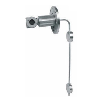
Page 25: J - Typical Installation In Tank For Stand Pipe Interface Level (Industrial Model)
Installation J - Typical Installation in Tank for Stand Pipe Interface Level (Industrial Model) FLANGE 4” ANSI B16,5 TANK DRAIN VENT INTERFACE LEVEL WATER DIAMETER 4” DIAMETER 1” DRAIN Figure 1.2 – Typical Installation for DT301 (J) 1.17... -
Page 26: Electronic Housing Rotation
DT301 – Operation, Maintenance and Instructions Manual Electronic Housing Rotation The electronic housing can be rotated in order for a better position for the digital display. To rotate it, use the housing rotation set screw, see figure 1.3. COVER LOCKING... - Page 27 Avoid routing signal wiring close to power cables or switching equipment. Plug and seal the unused outlet connection accordingly. The DT301 has protection against reverse polarity. Connection of the DT301 should be done as in Figure 1.7. Operating Areas 4-20mA and digital...
-
Page 28: Multidrop Operation
Bell 202 Modem using Hart Protocol. Each transmitter is identified by a unique address from 1 to 15. The DT301 is factory set to address 0, which means a non multidrop operation mode, allowing the transmitter to communicative with the Hand-Held Terminal, superimposing the communication on the 4- 20 mA signal. - Page 29 Installation Figure 1.8 – DT301 Diagram for Multidrop Connection 1.21...
-
Page 30: Installation In Hazardous Areas
Required” could be applied for Explosion Proof Version. (CSA Certification). The standard plugs provided by Smar are certified according to the standards at FM, CSA and CEPEL. If the plug needs to be replaced, a certified plug must be used. -
Page 31: Section 2 - Operation
Section 2 OPERATION The pressure sensor used by the DT301 Smart Concentration/ Density Transmitter is a capacitive cell, the same type used by the LD301 Smart Pressure Transmitter. This sensor is connected to a probe to accomplish the measures through of the pressure differential reading. The figure 2.1 schematizes the sensor used by the DT301. -
Page 32: Functional Description - Hardware
DT301 – Operation, Maintenance and Instructions Manual Functional Description - Hardware The transmitter blocks Diagram, as it shows the Figure 2.2, it describes the circuit used by the DT301 functionally. Probe The probe is the transmitter part that is directly in contact with the process. -
Page 33: Functional Description - Software
The work range of the transmitter defines the values for the currents 4 and 20 MA. The control current of the DT301 transmitter obeys the specifications of the NAMUR NE-43 norm. -
Page 34: Display
The indicator has the capacity to show the value, the engineering unit and the variable type, simultaneously with most of the state indications. See in the figure 2.4 a sample of a DT301 indication standard. -
Page 35: Section 3 - Configuration
In the case of the DT301, which can be configured a transmitter; the HART addressing is used as follows: Transmitter Mode - The "0" address causes the DT301 to control its output current and addresses "1" through "15" place the DT301 in the multidrop mode with current control. NOTE In case of multidrop network configuration for classified areas, the entity parameters allowed for the area shall be strictly observed. -
Page 36: Configuration Resources
LIST LIST Figure 3.1 – Configurator Figure 3.2 – CONF401 Screen Configuration Resources configurator, the DT301 firmware allows the following configuration features to By means of the HART be accessed: Transmitter identification and manufacturing data Primary variable trim – density ... -
Page 37: Manufacturing Data And Identification
4-20 mA signal, up to 2 km away from the transmitter. Manufacturing Data and Identification The following information about the DT301 manufacturing and identification data is available: TAG - 8-character alphanumeric field for transmitter identification. -
Page 38: Concentration Trim
Concentration Trim This trim is made with the DT301 installed in the process fluid. Catch a sample of the process fluid and determine the density or concentration in laboratory. Enter the trim menu to adjust the lower concentration, informing the value read in laboratory or another standard. -
Page 39: Temperature Trim
0.2 seconds. MEASUREMENT This function of configuration menu of the Smar programmer makes it possible to select the type of transference function the transmitter is expected to perform. There are several functions related with the measurement of density and concentration, and there is a special function which makes it possible to check the 4 to 20 mA current generated by the transmitter. -
Page 40: Engineering Unit Selection
The general equation to determine the solid percent is: %sol = a The table and the graph below indicate the application of the DT301 polynomial that relates Baume degree to solid percent, generating the polynomial: y = 0.004768x - 0.760813x... -
Page 41: Equipment Configuration
This function is applied to a higher number of applications. It relates three measurements: density, temperature and concentration. As the digital display used in DT301 is of 4 ½ digits, the maximum indicated value would be 19999. When selecting the unit, be certified that in your application the value won't surpass 19999. -
Page 42: Equipment Maintenance
DT301 – Operation, Maintenance and Instructions Manual NOTE The output current will be increased to 4 mA as the DT301 address is altered to another value than "0". DISPLAY INDICATION - the DT301 digital display is comprised of three distinct fields: an information field with icons indicating the active configuration status, a 4 ½... - Page 43 Configuration OPERATION COUNTER - Every time a change is made, there is an increment in the respective change counter for each monitored variable, according to the following list. The counter is cyclic, from 0 to 255. The monitored items are: LRV/URV: when any type of calibration is done;...
- Page 44 DT301 – Operation, Maintenance and Instructions Manual 3.10...
-
Page 45: Section 4 - Maintenance Procedures
When communicating using the configurator the user will be informed about any problem found by the transmitter self-diagnostics. The mistake messages always are alternate with the information shown in the first line of programmer Smar’s display. The table 4.1 lists the mistake messages. For more details on the corrective action, see referred table. ERROR MESSAGES... -
Page 46: Diagnostic Without Configurator
DT301 – Operation, Maintenance and Instructions Manual ERROR MESSAGES POTENTIAL SOURCE OF PROBLEM Sensor disconnected. XMTR MALFUNCTION Sensor failure. COLD START Start-up or reset due to power supplies failure. Output in constant mode. OUTPUT FIXED Transmitter in multidrop mode. -
Page 47: Procedure To Change The Dt301 Main Board
Check line resistance; it must be equal to or greater than 250 Ohm between the transmitter and the power supply. Power Supply Check output of power supply. The voltage at the DT301 terminals must be between 12 and 45 V, and ripple less than 500 mV. -
Page 48: Probe Set (16A, 16B, 19A Or 19B)
DT301 – Operation, Maintenance and Instructions Manual Figures 4.3 and 4.4 show transmitter's exploded view and will help you to understand the text below. The numbers between parentheses are relating to the enumeration of the items of the related drawing. -
Page 49: Probe Set (16A, 16B, 19A Or 19B)
Plug sensor connector and power supply connector to main board. Attach the display to the main board. Observe the four possible mounting positions (Figure 4.2). The Smar mark indicates up position. Figure 4.2 – Four Possible Positions of the Display Anchor the main board and display with their screw (3). -
Page 50: Returning Materials
Returning Materials If it becomes necessary to return the transmitter and/or configurator to Smar, simply contact our office, informing the defective instrument's serial number, and return it to our factory. In order to speed up analysis and solution of the problem, the defective item should be returned with the Service Request Form (SRF –... - Page 51 Maintenance Procedures Figure 4.3 - DT301 - Exploded View (Sanitary Model)
- Page 52 DT301 – Operation, Maintenance and Instructions Manual Figure 4.4 - DT301 - Exploded View (Industrial Model)
- Page 53 NOTE 1: For category A, it is recommended to keep, in stock, 25 parts installed for each set, and for category B, 50. NOTE 2: Includes terminal block, bolts, caps and identification plate without certification. NOTE 3: The main board of DT301 and probe are items. NOTE 4: O-rings are pack in packs of 12 units.
- Page 54 DT301 – Operation, Maintenance and Instructions Manual 400-0244 Sanitary Model Probe COD. RANGE Minimum Span 1.8 g/cm3 0,025 g/cm 2.5 g/cm 0,025 g/cm 5.0 g/cm 0,025 g/cm COD. Diaphragm Material Hastelloy C276 316L SST Tantalum Others – Specify COD. Fill Fluid...
-
Page 55: Section 5 - Technical Characteristics
The table 5.1 presents the filling fluids, which are available for the DT301, together with some physical properties and applications. VISCOSITY... -
Page 56: Performance Specifications
DT301 – Operation, Maintenance and Instructions Manual Static Pressure Limit 70 kgf/cm (7 MPa) (1015 PSI) Humidity Limits 0 to 100% RH Damping Adjustment 0 to 32 seconds in addition to intrinsic sensor response time (0.2 s) (Via Digital Communication). -
Page 57: Sanitary Concentration / Density Transmitter
Technical Characteristics Ordering Code MODEL SANITARY CONCENTRATION/DENSITY TRANSMITTER CODE Range Minimum Span 1.8 g/cm 0,025 g/cm 2.5 g/cm 0,025 g/cm Note: For the concentration units: °Brix, °Plato, °INPM, °GL and °Baumé, specify code1. 5.0 g/cm 0,025 g/cm CODE Wetted Parts Material Hastelloy C276 316L SST Probe in 316 SST and Diaphragms in Hastelloy C276... - Page 58 DT301 – Operation, Maintenance and Instructions Manual MODEL SANITARY CONCENTRATION/DENSITY TRANSMITTER (CONTINUATION) CODE Identification Plate FM: XP, IS, NI, DI EXAM ( DMT): EX-IA; NEMKO: EX-D CEPEL: EX-D, EX-IA Without Certification EXAM (DMT) GRUPO I, M1 EX-IA CODE Housing Material (1) (2)
-
Page 59: Industrial Concentration / Density Transmitter
Technical Characteristics MODEL INDUSTRIAL CONCENTRATION/DENSITY TRANSMITTER CODE Range Minimum Span 1.8 g/cm 0,025 g/cm Note: For the concentration units: °Brix, °Plato, °INPM, °GL and °Baumé, specify code1. 2.5 g/cm 0,025 g/cm 5.0 g/cm 0,025 g/cm CODE Diaphragm Material / Probe Hastelloy C276 / Hastelloy C276 316L SST / 316L SST Hastelloy C276 / 316L SST... -
Page 60: Optional Items
DT301 – Operation, Maintenance and Instructions Manual MODEL INDUSTRIAL CONCENTRATION/DENSITY TRANSMITTER (CONTINUATION) CODE Identification Plate FM: XP, IS, NI, DI EXAM ( DMT): EX-IA; NEMKO: EX-D CEPEL: EX-D, EX-IA Without Certification EXAM (DMT) GRUPO I, M1 EX-IA CODE Housing Material (1) (2) -
Page 61: Appendix A - Certifications Information
Crrgpfkz"C" " CERTIFICATIONS INFORMATION Gwtqrgcp"Fktgevkxg"Kphqtocvkqp" Consult www.smar.com for the EC declarations of conformity for all applicable European directives and certificates. ATEX Directive (94/9/EC) – “Electrical equipment and protective system intended for use in potential explosive atmospheres” The EC-Type Examination Certificate had been released by Nemko AS (CE0470) and/or DEKRA EXAM GmbH (CE0158), according to European Standards. -
Page 62: North American Certifications
Environmental Protection - Enclosure Types (Type X): Supplementary letter X meaning special condition defined as default by Smar the following: Saline Environment approved - salt spray exposed for 200 hours at 35ºC. (Ref: NEMA 250). - Ingress protection (IP W): Supplementary letter W meaning special condition defined as default by Smar the following: Saline Environment approved - salt spray exposed for 200 hours at 35ºC. -
Page 63: South American Certifications
The certificate number ends with the letter "X" to indicate that for the version of Density Transmitter model DT301 equipped with housing made of aluminum alloy, only can be installed in "Zone 0" if is excluded the risk of occurs impact or friction between the housing and iron/steel itens. -
Page 64: Identification Plate
FV523"⁄"Qrgtcvkqp."Ockpvgpcpeg"cpf"Kpuvtwevkqpu"Ocpwcn" " ABNT NBR IEC 60079-26:2008 Equipment with equipment protection level (EPL) Ga ABNT NBR IEC 60529:2009 Classification of degrees of protection provided by enclosures (IP Code) Kfgpvkhkecvkqp"Rncvg"cpf"Eqpvtqn"Ftcykpi" Identification Plate EXAM and NEMKO C06"... - Page 65 Egtvkhkecvkqpu"Kphqtocvkqp" " CEPEL C07"...
- Page 66 FV523"⁄"Qrgtcvkqp."Ockpvgpcpeg"cpf"Kpuvtwevkqpu"Ocpwcn" " C08"...
-
Page 67: Control Drawing
Egtvkhkecvkqpu"Kphqtocvkqp" " Control Drawing Factory Mutual (FM) C09"... - Page 68 FV523"⁄"Qrgtcvkqp."Ockpvgpcpeg"cpf"Kpuvtwevkqpu"Ocpwcn" " C0:"...
-
Page 69: Appendix B - Srf - Service Request Form
Appendix B SRF – Service Request Form Proposal No.: Density Transmitters Company: Unit: Invoice: COMMERCIAL CONTACT TECHNICAL CONTACT Full Name: Full Name: Function: Function: Phone: Extension: Phone: Extension: Fax: Fax: Email: Email: EQUIPMENT DATA Model: Serial Number: Sensor Number: Firmware Version: Technology: ( ) HART®... - Page 70 DT301 – Operation, Maintenance and Instructions Manual...
Need help?
Do you have a question about the DT301 and is the answer not in the manual?
Questions and answers