Table of Contents
Advertisement
Quick Links
Advertisement
Table of Contents

Subscribe to Our Youtube Channel
Related Manuals for SMAR LD290


Summary of Contents for SMAR LD290
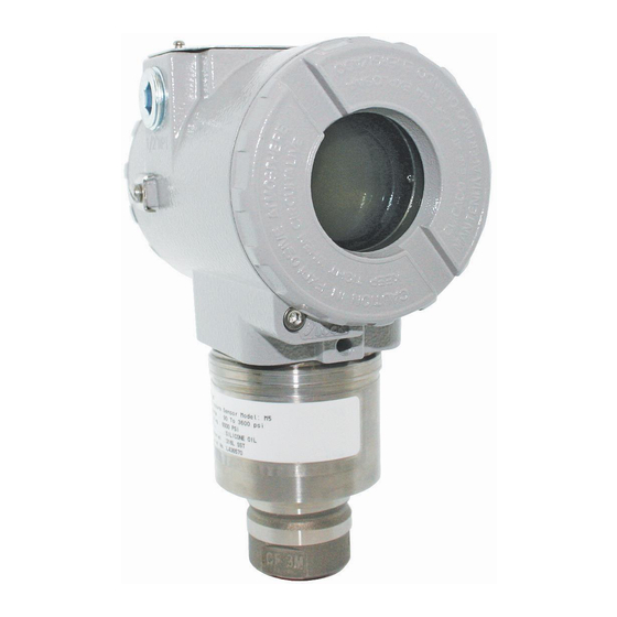
- Page 3 Introduction INTRODUCTION The LD290 is a pressure transmitter for gauge and level measurement. It is based on a field-proven capacitive sensor that provides reliable operation and high performance. A liquid crystal display can be added to provide additional operation and local indication. Its microprocessed electronic circuit permits a total interchangeability with Smar’s capacitive sensors.
- Page 4 Smar provides specific training to instruct and qualify such professionals. However, each country must comply with the local safety procedures,...
-
Page 5: Table Of Contents
Table of Contents TABLE OF CONTENTS SECTION 1 - INSTALLATION ........................1.1 GENERAL..................................1.1 MOUNTING .................................. 1.1 ELECTRONIC HOUSING ............................. 1.8 WIRING ..................................1.8 INSTALLATION IN HAZARDOUS AREAS ........................ 1.11 EXPLOSION/FLAME PROOF ............................ 1.11 INTRINSICALLY SAFE .............................. 1.11 SECTION 2 - OPERATION ........................2.1 FUNCTIONAL DESCRIPTION - SENSOR ........................ - Page 6 LD290 - Operation and Maintenance Instruction Manual...
-
Page 7: Section 1 - Installation
There are, however, ways of reducing the effects of temperature, humidity and vibration. The LD290 has a built-in temperature sensor to compensate for temperature variations. At the factory, each transmitter is submitted to a temperature cycle, and the characteristics under different temperatures are recorded in the transmitter memory. - Page 8 LD290 – Operation and Maintenance Instruction Manual Figure 1.1 (a) – Dimensional Drawing and Mounting Position for LD290...
- Page 9 Installation Figure 1.1 (b) – Dimensional Drawing and Mounting Position for LD290 - Sanitary...
- Page 10 LD290 – Operation and Maintenance Instruction Manual Figure 1.1 (c) – Dimensional Drawing and Mounting Position for LD290 – Sanitary...
- Page 11 Installation Figure 1.1 (d) – Dimensional Drawing and Mounting Position for LD290 – Level...
- Page 12 VIEW BY ‘’A’’ Mobile adjusting flange Diaphragm protection with screen PROBE LENGTH (OPTIONAL) O’RING VIEW BY ‘’C’’ VIEW BY ‘’BB’’ - DIMENSIONS ARE IN mm (in) Figure 1.1 (e) – Dimensional Drawing and Mounting Position for LD290 – Level (Insertion)
- Page 13 Figure 1.3 – Position of the Transmitter and Taps The location of pressure taps and the relative position of the transmitter are indicated in Table 1.1. Process Fluid Location of Taps LOCATION OF LD290 IN RELATION TO THE TAPS Top or Side Above the Taps...
-
Page 14: Electronic Housing
Use of twisted pair (22 AWG or greater than) cables is recommended. Avoid routing signal wiring close to power cables or switching equipment. The unused outlet connection should be plugged and sealed accordingly. The LD290 is protected against reverse polarity. However, it will not work in this situation. - Page 15 Figure 1.7 - Sensor Positions It is also recommended to ground the shield of shielded cables at only one end. The ungrounded end must be carefully isolated. Connection of the LD290 should be done as in Figure 1.8. POWER SUPPLY...
- Page 16 LD290 – Operation and Maintenance Instruction Manual NOTE Make sure that the transmitter is operating within the operating area as shown on the load curve (Figure 1.10). Figure 1.9 - Load Curve 1.10...
-
Page 17: Installation In Hazardous Areas
In Explosion-Proof installations the cable entries must be connected or closed using metal cable gland and metal blanking plug, both with at least IP66 and Ex-d certification. The standard plugs provided by Smar are certified according to CEPEL certificate. If the plug needs to be replaced, a certified plug must be used. - Page 18 LD290 – Operation and Maintenance Instruction Manual 1.12...
-
Page 19: Section 2 - Operation
Section 2 OPERATION Functional Description - Sensor The LD290 Series Pressure Transmitters use capacitive sensors (capacitive cells) as pressure sensing elements, as shown in Figure 2.1. Figure 2.1 – Capacitive Cell Where, and P are the pressures in chambers H and L CH = capacitance between the fixed plate on P side and the sensing diaphragm. -
Page 20: Functional Description - Hardware
DIGITAL CONVERTER DISPLAY Figure 2.2 – LD290 Block Diagram Hardware Power shall be supplied to the transmitter circuit using the signal line (2-wire system). The transmitter quiescent consumption is 3.6 mA; during operation, consumption may be as high as 21 mA, depending on the measurement and sensor status. - Page 21 DISPLAY SENDONDARY INDICATION INDICATOR Figure2.3 – LD290 – Software Block Diagram Output Calculates the current proportional to the process variable or manipulated variable to be transmitted on the 4-20 mA output depending on the configuration in OP-MODE. This block also contains the constant current function configured in OUTPUT.
-
Page 22: The Display
Monitoring During normal operation, the LD290 is in the monitoring mode. In this mode, indication alternates between the primary and secondary variable as configured by the user. See Figure. 2.5. The display indicates engineering units, values and parameters simultaneously with most status indicators. -
Page 23: Section 3 - Programming Using Local Adjustment
Section 3 PROGRAMMING USING LOCAL ADJUSTMENT The Magnetic Tool If the transmitter is fitted with a display, and configured for Complete Local Adjustment (using the internal jumper), the magnetic tool become a powerful configuration tool. If the transmitter is not fitted with a display, or is configured for Simple Local Adjustment (using the internal jumper) the adjustment capability is reduced to reranging. -
Page 24: Simple Local Adjustment
Table 3.2 - Local Adjustment Description NOTE For LD290 versions prior to a V6.00, the digital display shall be number 214-0108 as per spare parts list for LD290 V5.xx. For LD290 versions V6.xx, the digital display shall be number 400-0559, as per the updated... -
Page 25: Complete Local Adjustment
The local adjustment uses a tree structure where, by placing the magnetic tool in (Z) it is possible to browse the options of a branch and, by placing it in (S), details of the chosen option are shown. Figure 3.2 shows the LD290 available options. NORMAL... -
Page 26: Configuration Branch (Conf)
Figure 3.3 shows branch CONF with the available options. Figure 3.3 – Local Adjustment Configuration Tree * NOTE Among the units shown by LD290 only the units from Table 3.3 are valid. Configuration Branch (CONF) Z: Moves to the TRIM branch. -
Page 27: Range (Range)
Programming Using Local Adjustment Range (RANGE) Function Calibration (RANGE) presents the calibration options as a tree branch, as described on Figure 3.4. RANGE FUNCT UNIT ZERO ZERO DAMP SAVE SPAN SPAN DAMP Figure 3.4 – Local Range Tree Range Branch (RANGE) Z: Moves to the FUNCT function. - Page 28 LD290 – Operation and Maintenance Instruction Manual Lower Range Value Adjustment without Reference (LRV) Z: Moves to the LRV DECREASE function. S: Increases the Lower Value until the magnetic tool is removed or the maximum for the Lower Value is reached.
-
Page 29: Function (Funct)
Programming Using Local Adjustment Z: Moves to the DAMPING function. S: Decreases the Output in transmitter mode, increases the Upper Pressure Value until the magnetic tool is removed or the maximum for the Upper Value is reached. Damping (DAMP) Z: Moves to the DAMPING DECREASE function. S: Increases the damping time constant until the magnetic toll is removed or 32 seconds are reached. -
Page 30: Pressure Trim [Trim]
LD290 – Operation and Maintenance Instruction Manual Pressure Trim [TRIM] This field of the tree is used to adjust the digital reading according to the applied pressure. The pressure TRIM differs from RANGING WITH REFERENCE, since the TRIM is used to correct the measure and RANGING WITH REFERENCE reach only the applied pressure with the output signal of 4 to 20 mA. -
Page 31: Escape Local Adjustment [Esc]
Escape Local Adjustment [ESC] This branch of the main tree is used to leave the Local Adjustment mode, placing the Transmitter in the monitoring mode Z: Selects the OPERATION branch. S: Escapes to NORMAL DISPLAY mode, adjusting the LD290 in monitoring mode. - Page 32 LD290 – Operation and Maintenance Instruction Manual 3.10...
-
Page 33: Section 4 - Maintenance Procedures
Should the sensor eventually require maintenance, it may not be changed in the field. In this case, the possibly damaged sensor should be returned to SMAR for evaluation and, if necessary, repair. Refer to the item "Returning Materials" at the end of this Section. -
Page 34: Disassembly Procedure
Check the connection (flat cable, male and female connectors). ✓ Type of Sensor Connected to the Main Board Check if the sensor connected to the main board is the one specified for the LD290 model: Sensor type shall be hyper - High Performance. ✓... -
Page 35: Electronic Circuit
Maintenance Procedure Electronic Circuit To remove the circuit board (6), loosen the two screws (5) that anchor the board and hold the (7) spacers in the other side to avoid losing them. WARNING The board has CMOS components, which may be damaged by electrostatic discharges. Observe correct procedures for handling CMOS components. -
Page 36: Interchangeability
If it becomes necessary to return the transmitter and/or configurator to Smar, simply contact our office, informing the defective instrument's serial number, and return it to our factory. In order to speed up analysis and solution of the problem, the defective item should be returned with the Service Request Form (SRF –... - Page 37 Maintenance Procedure Figure 4.1 – Exploded View...
- Page 38 LD290 – Operation and Maintenance Instruction Manual ACCESSORIES ORDERING CODE DESCRIPTION SD-1 Magnetic Tool for local adjustment SPARE PARTS LIST FOR TRANSMITTER CATEGORY DESCRIPTION OF PARTS POSITION CODE (NOTE 1) HOUSING (NOTE 2) (NOTE 6) . Aluminum 1 and 15...
-
Page 39: Ordering Code For Housing
Maintenance Procedure Ordering Code for Housing CODE DESCRIPTION 400-1314 - 2 HOUSING: LD290 Option Communication Protocol 4-20 mA Option Electrical Connection ½ NPT M20 X 1.5 PG13.5 Option Material Aluminium (IP/Type) 316 SST (IP/Type) Aluminium – for saline atmospheres (IPW/Type X) - Page 40 LD290 – Operation and Maintenance Instruction Manual 209-0241 SPARE PART NUMBER FOR SANITARY PRESSURE SENSOR CODE Type Range Limits Range Limits Min. Max. Unit Min. Max. Unit Sanitary 12.5 mbar 5.02 201.09 Sanitary 62.5 2500 mbar 25.13 1005,45 Sanitary 0.625 157.1...
- Page 41 Maintenance Procedure 209-0241 SPARE PART NUMBER FOR FLANGED PRESSURE SENSOR Range Limits Range Limits COD. Type Min. Span Unit Min. Span Unit Min. Max. Min. Max. Level 1,25 -200 Note: The range can be extended up to 0.75 LRL and 1.2 URL with small degradation of Level -250 2,08...
- Page 42 LD290 – Operation and Maintenance Instruction Manual 4.10...
-
Page 43: Section 5 - Technical Characteristics
Section 5 TECHNICAL CHARACTERISTICS Functional Specifications Process Fluid Liquid, gas or steam. Two-wire, 4-20 mA controlled according to NAMUR NE43 Specification. See the figure below. Output Power Supply 12 to 45 Vdc. Max. Impedance (V power supply - 12VDC) / 0.02 . Load Limitation Indicator Optional 4½-digit numerical and 5-character alphanumerical LCD indicator. - Page 44 LD290 – Operation and Maintenance Instruction Manual Functional Specifications 14 MPa (138 bar) for ranges 2, 3, 4. 31 MPa (310 bar) for range 5. For Level Ranges ASME/DIN (models LD290L): 150#: 6 psia to 235 psi (-0,6 to 16 bar) to 199,4 °F (93 °C) 300#: 6 psia to 620 psi (-0,6 to 43 bar) to 199,4 °F (93 °C)
- Page 45 Technical Characteristics Functional Specifications PRESSURES TABLE FOR SEAL AND LEVEL FLANGES ASME B16.5 2017 STANDARD Maximum Temperature Allowed Material Pressure -29 to Group Class Maximum Pressure Allowed (bar) 19.5 17.7 15.8 13.8 12.1 10.2 51.7 51.7 51.5 50.3 48.3 46.3 42.9 41.4 40.3...
- Page 46 Injected aluminum or 316 SST with polyester painting with option 316 without painting. According to NEMA Type 4X or Type 4, IP66, IP66W*. *The IP66W sealing test (immersion) was performed at 1 bar for 24 hours. For any other situation, please consult Smar. IP66W tested for 200h to according NBR 8094 / ASTM B 117 standard.
-
Page 47: Ordering Code
Technical Characteristics Ordering Code MODEL GAGE PRESSURE TRANSMITTERS LD290M 4-20 mA Type Range Limits CODE Min. Max. Unit Gage 12.5 mbar Gage -1000 2500 mbar Gage Gage CODE Diaphragm Material and Fill Fluid 316L SST - Silicone Oil 316L SST – Inert Fluorolube Oil (2) Hastelloy C276 - Silicone Oil (1) Hastelloy C276 –... - Page 48 LD290 – Operation and Maintenance Instruction Manual MODEL GAGE PRESSURE TRANSMITTER (CONTINUATION) LD290M CODE Special Procedure Degrease Cleaning (Oxygen or Chlorine Service) CODE Output Signal 4-20 mA 0-20 mA CODE Housing Material (7) Aluminum (IP/TYPE) 316 SST for Saline Atmosphere (IPW/TYPEX) (6)
- Page 49 Technical Characteristics MODEL SANITARY PRESSURE TRANSMITTERS LD290S 4-20 mA Type Range Limits Range Limits CODE Min. Max. Unit Min. Max. Unit Sanitary 12.5 mbar 5.02 201.09 Sanitary 62.5 2500 mbar 25.13 1005,45 Sanitary 0.625 157.10 10054.50 Sanitary 6.25 55.15 90.65 799.89 CODE Diaphragm Material Hastelloy C276...
- Page 50 LD290 – Operation and Maintenance Instruction Manual MODEL SANITARY PRESSURE TRANSMITTERS (CONTINUATION) LD290S CODE Output Signal 4-20 mA 0-20 mA CODE Housing Material (4) Aluminum (IP/TYPE) 316 SST for Saline Atmosphere (IPW/TYPEX) (3) 316 SST (IP/TYPE) Copper Free Aluminum (IPW/TYPEX) (3)
- Page 51 Technical Characteristics MODEL LOW COST FLANGED PRESSURE TRANSMITTER LD290L 4-20 mA Range Limits Range Limits CODE Type Unit Unit Min. Max. Min. Max. Level 12.5 mbar 5.02 201.09 Level 62.5 2500 mbar 25.13 1005.45 Level 0.625 157.10 10054.50 Level 6.25 90.65 3625.94 CODE Diaphragm Material (Sensor) and Fill Fluid (Sensor)
- Page 52 LD290 – Operation and Maintenance Instruction Manual MODEL LOW COST FLANGED PRESSURE TRANSMITTER (CONTINUATION) LD290L CODE Special Procedure Degrease Cleaning (Oxygen or Chlorine Service) CODE Output Signal 4-20 mA 0-20 mA CODE Housing Material (9) Aluminum (IP/TYPE) 316 SST for saline atmosphere (IPW/TYPEX) (8)
- Page 53 Technical Characteristics MODEL PRESSURE TRANSMITTER WITH EXTENDED PROBE LD290I 4-20 mA Type Range Limits CODE Min. Max. Unit Level 12.5 mbar CODE Diaphragm Material and Fill Fluid 316L SST – Silicon Oil (1) CODE Local Indicator Without Indicator With Indicator CODE Fixing Transmitter User’s specification...
- Page 54 LD290 – Operation and Maintenance Instruction Manual MODEL PRESSURE TRANSMITTER WITH EXTENDED PROBE (CONTINUATION) LD290I CODE Output Signal 4-20 mA 0-20 mA CODE Housing Material (4) Aluminum (IP/TYPE) 316 SST for saline atmosphere (IPW/TYPEX) (3) 316 SST (IP/TYPE) Copper Free Aluminum (IPW/TYPEX) (3)
-
Page 55: European Directive Information
Consult www.Smar.com for the EC declarations of conformity and certificates. Authorized representative/importer located within the Community: Smar Europe BV De Oude Wereld 116 2408 TM Alphen aan den Rijn Netherlands ATEX Directive 2014/34//EU - "Equipment for explosive atmospheres” The EC-Type Examination Certificate is released by DNV GL Presafe AS (CE2460) and DEKRA Testing and Certification GmbH (CE0158). -
Page 56: Hazardous Locations Approvals
Maintenance and Repair The instrument modification or replaced parts supplied by any other supplier than authorized representative of Smar is prohibited and will void the Certification. Marking Label The instrument is marked with type of protection options. The certification is valid only when the type of protection is indicated by the user. - Page 57 Appendix A ATEX DNV GL Presafe A/S Explosion Proof (PRESAFE 18 ATEX 12410X) II 2 G Ex db IIC T6 Gb Ta -20 ºC to +60 ºC Options: IP66/68W or IP66/68 Special Conditions for Safe Use Repairs of the flameproof joints must be made in compliance with the structural specifications provided by the manufacturer.
- Page 58 - O número do certificado é finalizado pela letra “X” para indicar que para a versão do Transmissor de pressão, intrinsecamente seguro, modelo LD290 equipado com invólucro fabricado em liga de alumínio, somente pode ser instalado em “Zona 0”, se durante a instalação for excluído o risco de ocorrer impacto ou fricção entre o invólucro e peças de ferro/aço.
- Page 59 Appendix A camada de tinta de 70 a 150 µm e 120 a 200 µm, respectivamente, ou pintados com o plano de pintura P1 e P2 (Procedimento P-CQ-FAB-765-05) com tinta Resina Epoxy ou Poliuretano Acrílico Alifático com espessura de camada de tinta de 290 µm a 405 µm e 185 µm a 258 µm, respectivamente. - Os planos de pintura P1 e P2 são permitidos apenas para equipamento fornecido com plaqueta de identificação com marcação para grupo de gases IIB.
-
Page 60: Identification Plates And Control Drawing
LD290 – Certifications Information Identification Plates and Control Drawing FM Approvals DNV GL Presafe A/S / DEKRA Testing and Certication GmbH... - Page 61 Appendix A CEPEL (Centro de Pesquisa de Energia Elétrica)
- Page 62 LD290 – Certifications Information...
- Page 63 Appendix A FM Approvals...
- Page 64 LD290 – Certifications Information A.10...
-
Page 65: Appendix B - Srf - Service Request Form
(Please, describe the failure. Can the error be reproduced? Is it repetitive?) OBSERVATIONS USER INFORMATION Company: Contact: Title: Section: Phone: Extension: E-mail: Date: Signature: For warranty or non-warranty repair, please contact your representative. Further information about address and contacts can be found on www.smar.com/contactus.asp. - Page 66 LD290 – Appendix B...
Need help?
Do you have a question about the LD290 and is the answer not in the manual?
Questions and answers