Table of Contents
Advertisement
Quick Links
Advertisement
Table of Contents

Related Manuals for SMAR LD303


Summary of Contents for SMAR LD303
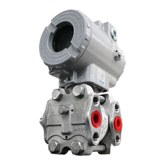
- Page 1 Profibus PA Pressure Transmitter L D 3 0 3 M E...
- Page 2 Specifications and information are subject to change without notice. Up-to-date address information is available on our website. web: www.smar.com/contactus.asp...
- Page 3 Using Profibus technology, with its capability to interconnect several devices, very large control schemes can be constructed. In order to be user friendly the function block concept was introduced. The LD303, like the rest of the 303 family, has some Function Blocks built in, like Analog Input and Totalizer Block.
- Page 4 Smar provides specific training to instruct and qualify such professionals. However, each country must comply with the local safety procedures,...
-
Page 5: Table Of Contents
TRANSDUCER BLOCK DIAGRAM ..........................3.2 PRESSURE TRANSDUCER BLOCK PARAMETER DESCRIPTION ................ 3.2 PRESSURE TRANSDUCER BLOCK PARAMETER ATTRIBUTES ................3.6 LD303 - CYCLIC CONFIGURATION .......................... 3.8 HOW TO CONFIGURE THE TRANSDUCER BLOCK ....................3.9 TABLE HANDLING ..................................3.11 HOW TO CONFIGURE THE ANALOG INPUT BLOCK ................... 3.15 HOW TO CONFIGURE THE TOTALIZER BLOCK .................... - Page 6 SOUTH AMERICA CERTIFICATION ............................A.3 ASIA CERTIFICATION ................................A.3 IDENTIFICATION PLATE AND CONTROL DRAWING .....................A.3 IDENTIFICATION PLATE ................................. A.3 CONTROL DRAWING ................................A.7 APPENDIX B – SRF – SERVICE REQUEST FORM .................. B.1 APPENDIX C – SMAR WARRANTY CERTIFICATE ................. C.1...
- Page 7 Installation Flowchart Basic Installation Flowchart Start Has the transmitter been configured Field Installation. in bench for the application ? Install the transmitter in protected areas from weather proof. Configure the transmitter ( section 1 and section 3). Verify area classification and its respective practices.
- Page 8 LD303 Operation and Maintenance Instruction Manual VIII...
-
Page 9: Section 1 - Installation
There are, however, ways of reducing the effects of temperature, humidity and vibration. The LD303 has a built-in temperature sensor to compensate for temperature variations. At the factory, each transmitter is submitted to a temperature cycle process, and the characteristics under different pressures and temperatures are recorded in the transmitter memory. - Page 10 LD303 - Operation and Maintenance Instruction Manual Figure 1.1 (a) – Dimensional Drawing and Mounting Position - Differential, Flow, Gage, Absolute and High Static Pressure Transmitters with Mounting Bracket...
- Page 11 Installation Figure 1.1 (b) – Dimensional Drawing and Mounting Position - Flanged Pressure Transmitter with Integral Flange...
- Page 12 LD303 - Operation and Maintenance Instruction Manual Figure 1.1 (c) – Dimensional Drawing and Mounting Position - Flanged Pressure Transmitter with Slip-on Flange...
- Page 13 Installation Figure 1.1 (d) – Dimensional Drawing and Mounting Position - Flanged Pressure Transmitter with Housing...
- Page 14 LD303 - Operation and Maintenance Instruction Manual Figure 1.1 (e) – Dimensional Drawing and Mounting Position - Sanitary Transmitter without Extension...
- Page 15 Installation Figure 1.1 (f) – Dimensional Drawing and Mounting Position - Sanitary Transmitter with Extension...
- Page 16 Table 1.1 - Location of Pressure Taps WALL OR PANEL MOUNTING (See section 5 – spare parts list for mounting brackets available) Figure 1.2 – Drawing Mounting of LD303 on the Panel or Wall Figure 1.3 - Position of the Transmitter and Taps...
-
Page 17: Housing Rotation
Installation NOTE Except for dry gases, all impulse lines should slope at the ratio 1:10, in order to avoid trapping bubbles in the case of liquids, or condensation from steam or wet gases. Housing Rotation The housing can be rotated in order to get the digital display in better position. To rotate it, releases the Housing Rotation Set Screw. - Page 18 Various types of Profibus devices may be connected on the same bus. The LD303 is powered via the bus. The limit for such devices is according to the DP/PA coupler limitation for one bus for non-intrinsically safe requirement.
-
Page 19: Bus Topology And Network Configuration
Installation When the sensor is in the horizontal position, the weight of the fluid pushes the diaphragm down, making it necessary a Lower Pressure Trim see Figure 1.8. DIAPHRAGM SENSOR HEAD OF THE FLUID DIAPHRAGM SENSOR SENSOR IN THE VERTICAL POSITION SENSOR IN THE HORIZONTAL POSITION Figure 1.8 - Sensor Positions NOTE... -
Page 20: Intrinsic Safety Barrier
Use of DF47 is recommended. See more in http://www.smar.com/products/df47-12.asp. Jumper Configuration In order to work properly, the jumpers J1 and W1 located in the LD303 main board must be correctly configured (See Table 1.2). This jumper enables the simulation mode parameter in the AI block. -
Page 21: Power Supply
Installation Power Supply The LD303 receives power from the bus via the signal wiring. The power supply may come from a separate unit or from another device such as a controller or DCS. The voltage should be between 9 to 32 Vdc for non-intrinsic safe applications. - Page 22 LD303 - Operation and Maintenance Instruction Manual 1.14...
-
Page 23: Section 2 - Operation
Section 2 OPERATION The LD303 Series Pressure Transmitters use capacitive sensors (capacitive cells) as pressure sensing elements, as shown in Figure 2.1. This is exactly the same sensor as the LD301 series uses, the sensor modules are therefore interchangeable. Figure 2.1 - Capacitive Cell... -
Page 24: Functional Description - Electronics
LD303 - Operation and Maintenance Instruction Manual As the distance (d) between the fixed plates CH and CL is constant. It is possible to conclude that the expression (CL - CH)/(CL + CH) is proportional to ∆d and, therefore, to the differential pressure to be measured. -
Page 25: Display
Operation Power Supply Takes power of the loop-line to power the transmitter circuitry. Power Isolation Isolates the signals to and from the input section, the power to the input section must be isolated. Display Controller Receives data from the CPU identifying which segments on the liquid crystal Display use to turn on. The controller drives the backplane and the segment control signals. - Page 26 LD303 - Operation and Maintenance Instruction Manual...
-
Page 27: Section 3 - Configuration
The 303 Smar family is integrated in Profibus View from Smar and Simatic PDM from Siemens. It is possible to integrate any 303 Smar devices into any configuration tool for Profibus PA devices. It is necessary to provide a Device Description or Drive according to the configuration tool. -
Page 28: Transducer Block Diagram
LD303 - Operation and Maintenance Instruction Manual Transducer Block Diagram Figure 3.1 – Transducer Block Diagram Pressure Transducer Block Parameter Description Parameter Description This parameter allows to save and to restore data according to factory and user calibration procedures. It has the following options: 1, "Factory Cal Restore",... - Page 29 Configuration Parameter Description This parameter is used to enable the zero cutoff. DEAD BAND_BYPASS { 1, “True” } { 0, “False” } This parameter is used to indicate EEPROM saving process. EEPROM_FLAG { 0, “False” } { 1, “True” } This parameter is used to enable factory characterization curve.
- Page 30 LD303 - Operation and Maintenance Instruction Manual Parameter Description SECONDARY_VALUE_2_UNIT This parameter contains the units of the SECONDARY_VALUE_2 defined by the manufacturer This parameter contains the index code for the material of the diaphragm, which comes in contact SENSOR_DIAPHRAGM_MATERIAL with the process media.
- Page 31 Configuration Parameter Description This parameter contains the temperature (e.g. sensor temperature used for measurement TEMPERATURE compensation) with the associated status used within the transducer. The unit of TEMPERATURE is the TEMPERATURE_UNIT. This parameter contains the units of the temperature. The unit codes are: K (1000), °C (1001), and TEMPERATURE_UNIT °F (1002).
-
Page 32: Pressure Transducer Block Parameter Attributes
LD303 - Operation and Maintenance Instruction Manual Pressure Transducer Block Parameter Attributes Parameter Mandatory / Rel. Object usage/ Default – Down-load Parameter Data Type Storage Size Access Optional View Index Type Type of value Order (Class) transport ... Standard Parameter... - Page 33 Configuration Parameter Mandatory / Rel. Object usage/ Default – Down-load Parameter Data Type Storage Size Access Optional View Index Type Type of value Order (Class) transport TAB_MIN_NUMBER See explanation about table handling TAB_OP_CODE See explanation about table handling TAB_STATUS See explanation about table handling TAB_X_Y_VALUE See explanation about table handling MAX_SENSOR_VALU...
-
Page 34: Ld303 - Cyclic Configuration
LD303 shows details such as, hardware and software revision, device bus timing and information about cyclic data exchange. LD303 has two function blocks: one AI (Analog Input) and one TOT (Totalizer). It also has the empty module for applications where not all function blocks are necessary. The following cyclic order of the blocks should be respected: AI and TOT. -
Page 35: How To Configure The Transducer Block
The Profibus View from Smar and Simatic PDM (Process Device Manager), from configuration softwares, for example, can configure many parameters of the Input Transducer block. See figure 3.2 and 3.3. - Page 36 LD303 - Operation and Maintenance Instruction Manual Figure 3.3 - Function and Transducers Blocks – Simatic PDM To make the configuration of Transducer Block, we need to select the menu "Device". Use this menu: - To change the device address;...
-
Page 37: Table Handling
Configuration Using this window, the user can set the Primary Value Type according to his application, selecting "Pressure" or “Flow". Also, the user can select the Linearization Type, choosing "No Linearization", "Square Root" or "User Defined (Table)”. When the user desires to make the square root of pressure is necessary to set Primary Value Type to "Flow". - Page 38 LD303 - Operation and Maintenance Instruction Manual Figure 3.6 – Parameters of a Table TAB_MAX_NUMBER is the maximum size of the table in the device. TAB_MIN_NUMBER is the minimum size of the table in the device. The modification of a table in the device influences the measurement algorithms of the device.
- Page 39 Configuration Go to "Device Off Line Configuration Transducer" window and select "user defined (table)". Figure 3.7 – Transducer Offline Configuration Screen Using the menu Table, the user can configure the points. The user also can read the configurable table and write a new one. In this case, the table must be monotonous increasing;...
- Page 40 LD303 - Operation and Maintenance Instruction Manual See the Transducer Block configuration screens below using the Profibus View. Figure 3.9 - Scale Units for Transducer Block Figure 3.10 - Transducer Configuration Screen 3.14...
-
Page 41: How To Configure The Analog Input Block
Configuration Figure 3.11 - Transducer Configuration – User Table Screen How to Configure the Analog Input Block The Analog Input block takes the input data from the Transducer block, selected by channel number, and makes it available to other function blocks at its output. The transducer block provides the input unit of the Analog Input, and when the unit is changed in the transducer, the PV_SCALE unit is changed too. - Page 42 LD303 - Operation and Maintenance Instruction Manual The user can set the block mode operation. The user can select PV (Primary Value), Sec Value 1 (Secundary Value 1) or Sec Value 2 (Secundary Value 2) for the channel. Scale of input value.
- Page 43 Configuration Selecting the window "Advanced Settings", the user can configure the conditions for alarms and warnings, as well the fail safe condition. Please, see the window: The user can set Alarm/Warning limits. The fail safe conditions. Figure 3.13 – Advanced Settings for Analog Input Block The user can set the mode block...
- Page 44 LD303 - Operation and Maintenance Instruction Manual Figure 3.15 - Basic Settings for Analog Input Block Figure 3.16 Advanced Settings for Analog Input Block 3.18...
-
Page 45: How To Configure The Totalizer Block
Configuration Figure 3.17 - Configuration for Analog Input Block How to configure the Totalizer Block The Totalizer function block takes the input data from the Transducer block, selected by channel number, and integrates over the time. This block is normally used to totalize flow, giving total mass or volume over a certain time, or totalize power, giving the total energy. - Page 46 LD303 - Operation and Maintenance Instruction Manual The user can set the block mode. The user can choose the channel value. The user can set the conditions for totalization and the unit. Figure 3.18 – Basic Settings for Totalizer Block Choosing the "Advanced Settings"...
- Page 47 Configuration The user can set the mode block operation. The user can monitor the totalizer output parameter and verify the current state alarm. Figure 3.20 - Block Mode for Totalizer Block The user can select: Totalize, Reset and Preset and enter the value for preset operation.
- Page 48 LD303 - Operation and Maintenance Instruction Manual Figure 3.22 - Basic Settings for Totalizer Block Figure 3.23 - Advanced Settings for Totalizer Block 3.22...
- Page 49 Configuration Figure 3.24 - Block Mode for Totalizer Block Figure 3.25 – Set / Reset for Totalizer Block 3.23...
-
Page 50: Lower And Upper Trim
There are two types of trim available: Lower Trim: It is used to trim the reading at the lower range. The operator informs the LD303 the correct reading for the applied pressure. The most common discrepancy is the lower reading. - Page 51 Configuration The parameter SENSOR_UNIT should be configured according to the Engineering Unit wished for calibrating the device. After the selection, this key should be pressed to complete the operation The Engineering Units can be choosen from the Sensor Units list box. Figure 3.26 –...
-
Page 52: Via Local Adjustment
LD303 - Operation and Maintenance Instruction Manual For this case, a sensor range 3 is used: The LRL is -25400 mmH2O or -1000 inH2O. The Lower Calibration Point should be entered. This value must be inside of the Sensor range limits allowed for each type of sensor. -
Page 53: Characterization Trim
The Figure 3.29 shows the window of Simatic PDM to characterize a new curve. Note that FACTORY_CURVE_X indicates the applied pressure according to standard pressure source and FACTORY_CURVEX_Y indicates measured pressure value to LD303. 3.27... - Page 54 LD303 - Operation and Maintenance Instruction Manual The number of points is configured in parameter FACTORY_CURVE_LENGTH, being in the maximum 5 points. The entry points will be configured in the FACTORY_CURVE_X and of output in the FACTORY_CURVE_Y. The Parameter FACTORY_CURVE_BYPASS controls the enabling/disabling of the curve and has the following options: "Disable ",...
-
Page 55: Sensor Information
Configuration Sensor Information The main information about the transmitter can be accessed selecting the Transducer block folder option as shown on the next figure. The sensor information will be displayed as shown below: Sensor Construction Information Figure 3.30 – Transducer Block – Sensor Information Some parameters are only factory configured (e.g. -
Page 56: Sensor Data Reading
Sensor Data Reading All time that transmitter LD303 is on, is verified if the serial number of the sensor in the sensor board is the same that the recorded serial number in EEPROM in the main board. When these numbers are different (a swap of sensor set or main board was carried through) the data stored in the EEPROM of sensor board is copied to the EEPROM of the main board. -
Page 57: Transducer Display - Configuration
"Programming Using Local Adjustment". It is significantly the resources on this transducer display, also all the Series 303 field devices from SMAR has the same methodology to handle with it. So, since the user has learned once, he is capable to handle all kind of field devices from SMAR. 3.31... -
Page 58: Definition Of Parameters And Values
LD303 - Operation and Maintenance Instruction Manual All function block and transducers defined according Profibus PA have a description of their features written, by the Device Description Language. This feature permits those third parties configuration tools enabled by Device Description Service technology can interpret these features and make them accessible to configure. - Page 59 Configuration In case you wish to visualize a certain tag, opt for the index relative equal to "tag". To configure other parameters just select "LCD-II" up to "LCD-VI" windows: The option "Write" should be selected in order to execute the upgrade of local adjustment...
- Page 60 LD303 - Operation and Maintenance Instruction Manual Selecting "None", only the last chosen monitoring parameter will be shown at LCD. Figure 3.37 - Parameters for Local Adjustment Configuration 3.34...
-
Page 61: Local Adjustment Tree - Quick Guide
Configuration Local Adjustment Tree - Quick Guide 3.35... -
Page 62: Programming Using Local Adjustment
It also enables pre- configuration of the communication. See figure 3.39. The table 3.5 describes what the actions in the S and Z holes cause in the LD303 when the local adjustment is enable. -
Page 63: J1 Jumper Connection
Configuration Figure 3.39 – Local Adjustment Holes Action in Cause Starts and moves among the available functions. Selects the function showed in the indicator. Table 3.5 – Purpose of the holes on the Housing J1 Jumper Connection If J1 jumper (see figure 3.40) is connected to the bolts under the word ON parameters could be simulated, through SIMULATE parameter, of the function blocks. - Page 64 LD303 - Operation and Maintenance Instruction Manual Place the magnetic tool in S orifice and In order to start the local wait for 5 seconds. adjustment, place the magnetic tool in Z orifice and wait until letters MD are displayed.
- Page 65 In order to increment the value, insert and keep the tool in S orifice until getting the desired value. Figure 3.44 - Step 4 - LD303 In order to select the In order to decrement next function, the upper the upper value, place...
- Page 66 LD303 - Operation and Maintenance Instruction Manual Cyclical Diagnosis Via cyclic communication is possible to verify diagnostics from the LD303 using the Profibus Master Class 1 or even via acyclic communication via Master Class 2. The Profibus-PA devices provide up to 4 standard diagnoses bytes via Physcial Block (see figure 3.47 and 3.48) and when the most...
- Page 67 Configuration Unit_Diag_Bit(37) = "Maintenance required" Unit_Diag_Bit(38) = "Characteristics invalid" Unit_Diag_Bit(39) = "Ident_Number violation" ;Byte 03 Unit_Diag_Bit(40) = "Not used 40" Unit_Diag_Bit(41) = "Not used 41" Unit_Diag_Bit(42) = "Not used 42" Unit_Diag_Bit(43) = "Not used 43" Unit_Diag_Bit(44) = "Not used 44" Unit_Diag_Bit(45) = "Not used 45"...
- Page 68 Identifier_Number_Selector is changed from "Profile Specific" to "Manufacturer Specific" or vice- versa, one must wait 5 seconds while is saved. Then, turn the LD303 off and turn it on again. So, the Identifier Number is updated to the communication level. If the equipment is in "Profile Specific"...
-
Page 69: Section 4 - Maintenance Procedures
It should be grounded at one end only. Power Supply Check power supply output. The voltage must be between 9 - 32 VDC at the LD303 terminals. Noise and ripple should be within the following limits: a) 16 mV peak to peak from 7.8 to 39 KHz. -
Page 70: Disassembly Procedure
LD303 - Operation and Maintenance Instruction Manual If the problem is not presented in the table above follow the Note below: NOTE The Factory Init should be tried as a last option to recover the equipment control when the equipment presents some problem related to the function blocks or the communication. -
Page 71: Electronic Circuit
Maintenance Procedures Cleaning should be done carefully in order to avoid damaging the delicate isolating diaphragms. Use of a soft cloth and a non-acid solution is recommended. The oscillating circuit is a part of the sensor and the replacement of one implies replacing the other. To remove the sensor from the electronic housing, the electrical connections (in the field terminal side) and the main board connector must be disconnected. -
Page 72: Electronic Circuit
Plug sensor connector and power supply connector to main board. Attach the display to the main board. Observe the four possible mounting positions. (Figure 4.3 - Four Possible Positions of the Display). The SMAR mark indicates up position. Figure 4.3 - Four Possible Positions of the Display Anchor the main board and display with their screws (3). -
Page 73: Upgrading Ld301 To Ld303
The sensor and casing of the LD301 is exactly the same as the LD303. By changing the circuit board of the LD301 it becomes a LD303. The display on LD301 version 5.XX is the same as on LD303 and can therefore be used with the LD303 upgrade circuit board. With a LD301 version three or earlier, that display can not be used. - Page 74 LD303 - Operation and Maintenance Instruction Manual Figure 4.4 - Exploded View...
- Page 75 Maintenance Procedures SPARE PARTS LIST CATEGORY DESCRIPTION OF PARTS POSITION CODE (NOTE 1) HOUSING, Aluminum (NOTE 2) ½ - 14 NPT 400-0291 M20 x 1.5 400-0292 PG 13.5 DIN 400-0293 HOUSING, 316 SS (NOTE 2) ½ - 14 NPT 400-0294 M20 x 1.5 400-0295 PG 13.5 DIN...
- Page 76 LD303 - Operation and Maintenance Instruction Manual SPARE PARTS LIST CATEGORY DESCRIPTION OF PARTS POSITION CODE (NOTE 1) O’RINGS (NOTE 3) Flange, BUNA-N 203-0401 Flange, VITON 203-0402 Flange, TEFLON 203-0403 Flange, ETHYLENE/PROPYLENE 203-0404 Flange, TEFLON with spring LOADED (NOTE 6)
-
Page 77: Smar Insulator Kit
Hydrogen to the diaphragm of the Remote Seal or of the Level Transmitter. The figure 6.3 shows the following parts that constitute the Smar Insulator Kit: Teflon Gasket (6), Nonmetallic Insulating Sleeve (4), Mica Washers (3) and Steel Washers (2). - Page 78 LD303 - Operation and Maintenance Instruction Manual 1 - Bolt 2 – Steel Washer 3 – Mica Washer 4 – Nonmetallic Isolating Sleeve 5 – Sealed Flange 6 – Sealing Gasket in Teflon 7 – Process Flange 8 – Nuts Figure 4.5 –...
- Page 79 Maintenance Procedures INSULATOR KIT SPARE PARTS: LD300L MODELS WITHOUT EXTENSION MODELS WITH EXTENSION ØN GROUP NORM LD300L / SR301T LD300L / SR301E 400-0861-11X01 400-0861-11X11 1” 400-0861-12X01 400-0861-12X11 400-0861-13X01 400-0861-13X11 400-0861-21X01 400-0861-21X11 1.1/2” 400-0861-22X01 400-0861-22X11 400-0861-23X01 400-0861-23X11 400-0861-31X01 400-0861-31X11 2” 400-0861-32X01 400-0861-32X11 400-0861-33X01 400-0861-33X11...
- Page 80 LD303 - Operation and Maintenance Instruction Manual SPARE PARTS: LD300L DRAIN GASKET VALVE ØN GROUP NORM STAINLESS TEFLON COPPER GRAFOIL STEEL 316L 1” 400-0425 400-0426 400-0427 400-0428 400-0429 400-0430 1.1/2” 400-0431 400-0432 400-0433 2” 400-0434 400-0435 400-0436 3” 400-0437 400-0438 400-0439 4”...
- Page 81 Maintenance Procedures RTJ SPARE PARTS: LD300L (without Extension) DRAIN METALLIC RING VALVE ØN GROUP NORM RING STAINLESS STAINLESS STEEL 316L STEEL 316L 400-0887 400-0888 1” 400-0888 400-0888 1500 400-0889 2500 400-0890 400-0891 1.1/2” 400-0891 400-0891 1500 400-0893 2500 400-0792 ANSI B 16.20 RTJ 400-0892 400-0893 2”...
-
Page 82: Application With Halar
LD303 - Operation and Maintenance Instruction Manual METALLIC RING ø CLASS NORM Ring 316L SST 1500 400-0899 3” 2500 400-0898 ANSI B 16.20 RTJ 1500 400-0903 4” 2500 400-0902 Table 5.5 - LD300L – Special models for Gasket in Steel – Without Extension... - Page 83 Maintenance Procedures Figure 4.8 – TPE Software Screen 4.15...
-
Page 84: Ordering Code For The Sensor
LD303 - Operation and Maintenance Instruction Manual Ordering Code for the Sensor 204 – 0301 SENSOR FOR DIFFERENTIAL , FLOW, GAGE, ABSOLUTE AND HIGH STATIC PRESSURE TRANSMITTER Range Limits Range Limits Min. Min. COD Type Unit Unit Span Span Min. - Page 85 Maintenance Procedures 204-0301 SENSOR FOR FLANGED PRESSURE TRANSMITTER Range Limits Range limits Min. Min. COD. Unit Unit Span Span Min. Max. Min. Max. Note: The range can be extended up to 0.75 LRL and 1.2 URL with small degradation of accuracy. The upper 1.25 -200 range value must be limited to the flange rating.
- Page 86 LD303 - Operation and Maintenance Instruction Manual 204-0301 SENSOR FOR FLANGED PRESSURE TRANSMITTER (CONTINUATION) CODE Flanges Bolts and Nuts Material Plated Carbon Steel (Default) (16) Hastelloy C276 316 SST Carbon Steel (ASTM A193 B7M) (1) (16) CODE Flange thread for fixing accessories (adapters, manifolds, mounting brackets, etc) 7/16”...
- Page 87 Maintenance Procedures 204-0301 SENSOR FOR SANITARY PRESSURE TRANSMITTER Range Limits Range limits Min. Min. COD. Unit Unit Span Span Min. Max. Min. Max. Note: The range can be extended up to 0.75 LRL and 1.2 URL with small degradation of accuracy. The upper range 1.25 -200 value must be limited to the flange rating.
- Page 88 LD303 - Operation and Maintenance Instruction Manual 204-0301 SENSOR FOR SANITARY PRESSURE TRANSMITTER (CONTINUATION) CODE Flanges Bolts and Nuts Material Plated Carbon Steel (Default) 13) Hastelloy C276 316 SST Carbon Steel (ASTM A193 B7M) (1) (13) CODE Flange thread for fixing accessories (adapters, manifolds, mounting brackets, etc) 7/16”...
-
Page 89: Section 5 - Technical Characteristic
Field Device Ex n1 IIC T4 (FM, CSA, NEMKO, EXAM, CEPEL) Authorized representative in European Community Smar Gmbh-Rheingaustrasse 9-55545 Bad Kreuzanach PED Directive (97/23/EC) – Pressure Equipment Directive This product is in compliance with the directive and it was designed and manufactured in accordance with sound engineering practice using several standards from ANSI, ASTM, DIN and JIS. - Page 90 LD303 – Operation and Maintenance Instruction Manual Functional Specifications 0 to 100% RH Humidity Limits User configurable from 0 to 128 seconds (via digital communication). Damping Adjustment Performance Specifications Span starting at zero, temperature of 25°C (77°F), atmospheric pressure, power supply of 24 Vdc, silicone oil fill fluid, Reference Conditions isolating diaphragms in 316L SST and digital trim equal to lower and upper range values.
- Page 91 Complies with NEMA 4X/6P, IP66 or IP66W*, IP68 or IP68W*. *The IP66/68W sealing test (immersion) was performed at 1 bar for 24 hours. For any other situation, please consult Smar. IP66/68W tested for 200h to according NBR 8094 / ASTM B 117 standard. Blank Flange:...
-
Page 92: Technical Characteristics Of High Performance - Code L1
LD303 – Operation and Maintenance Instruction Manual Technical Characteristics of High Performance - CODE L1 High Performance option (code L1) is available under the following conditions only: Differential and Gage Application 50 kPa -200 200 inH -250 250 kPa 36 psi... -
Page 93: Ordering Code
Technical Characteristics Ordering Code MODEL DIFFERENTIAL , FLOW, GAGE, ABSOLUTE AND HIGH STATIC PRESSURE TRANSMITTER LD303 PROFIBUS PA Range Limits Range Limits Min. Min. COD. Type Unit Unit Span Span Min. Max. Min. Max. Differential and Flow 0.05 NOTE: The range can be extended up to 0.75 LRL* and Differential and Flow 0.13... - Page 94 LD303 – Operation and Maintenance Instruction Manual NOTAS (13) Disponível somente para transmissor diferencial, faixa D4 ou H4, rosca 7/16 (1) Atende às recomendações da norma NACE MR-01-75/ISO 15156. UNF ou M10 x 1.5 para fixação de acessórios. (2) Não disponível para modelos absolutos e aplicações em vácuo.
- Page 95 Technical Characteristics MODEL FLANGED PRESSURE TRANSMITTERS LD303 PROFIBUS PA Range Limits Range limits Min. COD. Unit Min. Span Unit Span Min. Max. Min. Max. Note: The range can be extended up to 0.75 LRL and 1.2 URL with small degradation of accuracy.
-
Page 96: Optional Items
LD303 – Operation and Maintenance Instruction Manual FLANGED PRESSURE TRANSMITTERS (CONTINUATION) LD303 COD. Flanges Bolts and Nuts Material Plated Carbon Steel (Default) (20) Carbon Steel (ASTM A193 B7M) (1) (20) 316 SST Hastelloy C276 COD Flange Thread for Fixing Accessories (Adapters, Manifolds, Mounting Brackets, etc) 7/16”... - Page 97 Technical Characteristics MODEL SANITARY PRESSURE TRANSMITTERS LD303 PROFIBUS PA CODE Range Limits Range Limits Min. Span Unit Min. Span Unit Min. Max. Min. Max. 1.25 -200 Note: The range can be extended up to 0.75 LRL and 1.2 URL with small -250 2.08...
-
Page 98: Optional Items
LD303 – Operation and Maintenance Instruction Manual SANITARY PRESSURE TRANSMITTERS (CONTINUATION) LD303 CODE Flange Bolts and Nuts Material Plated Carbon Steel (Default) (15) Carbon Steel (ASTM A193 B7M) (1) (15) 316 SST Hastelloy C276 CODE Flange Thread for Fixing Accessories (Adapters, Manifolds, Mounting Brackets, etc) 7/16”... -
Page 99: Appendix A - Certifications Information
Other Approval Sanitary Approval Certifier Body: 3A Sanitary Standards Model Designations: LD303 with or without extension Sensors and Sensor Fittings and Connections Used on Fluid Milk and Milk Products, Number: 74-03. (Authorization No. 873). Documents for manuals Label Plate: 101A-1797 •... -
Page 100: North American Certifications
LD303 – Certifications Information North American Certifications FM Approvals (Factory Mutual) Certificate N: FM 3006959 and 3015629 Explosion-proof for Class I, Division 1, Groups A, B, C and D. Dust-ignition proof for Class II, Division 1, Groups E, F and G; Class III, Division 1. -
Page 101: South America Certification
Appendix A 2. For enclosures of the transmitters made of aluminum impact and friction hazards shall be considered when the transmitter is used in category II 1 G according to EN 50284 clause 4.3.1 3. The diode safety barrier shall have a linear resistive output characteristic. 4. - Page 102 LD303 – Certifications Information NEMKO and EXAM CEPEL NEPSI...
- Page 103 Appendix A WITHOUT APPROVAL Identification of Intrinsically safe and Explosion Proof for saline atmospheres: • NEMKO and EXAM...
- Page 104 LD303 – Certifications Information CEPEL...
-
Page 105: Control Drawing
Appendix A Control Drawing Factory Mutual (FM) - Page 106 LD303 – Certifications Information...
-
Page 107: Appendix B - Srf - Service Request Form
E-mail: Date: Signature: For warranty or non-warranty repair, please contact your representative. Further information about address and contacts can be found on www.smar.com/contactus.asp. NOTE (1) This field should be filled out by the Smar. ® (3) Required for Wireless HART devices. - Page 108 LD303 – Operation and Maintenance Instruction Manual...
-
Page 109: Appendix C - Smar Warranty Certificate
Equipments and products excluded from the warranty clauses must be approved by the client prior to the service execution. 11. In cases of repairs, the client shall be responsible for the proper product packaging and SMAR will not cover any damage occurred in shipment. - Page 110 13. It is the customer’s responsibility to clean and decontaminate products and accessories prior to shipping them for repair, and SMAR and its dealer reserve themselves the right to refuse the service in cases not compliant to those conditions. It is the customer’s responsibility to tell SMAR and its dealer when the product was utilized in applications that contaminate the equipment with harmful products during its handling and repair.
Need help?
Do you have a question about the LD303 and is the answer not in the manual?
Questions and answers