RGBlink mini-edge User Manual
Hide thumbs
Also See for mini-edge:
- Quick start manual (26 pages) ,
- User manual (109 pages) ,
- User manual (114 pages)
Table of Contents
Advertisement
Quick Links
Advertisement
Table of Contents

Related Manuals for RGBlink mini-edge


Summary of Contents for RGBlink mini-edge
- Page 1 User Manual...
-
Page 2: Table Of Contents
2.3 Connecting Microphone and External Monitoring Devices ....22 2.4 Connecting USB for Streaming and Recording ......... 23 2.5 Connecting Router ..................24 2.6 Plugging in Power ..................24 © Xiamen RGBlink Science & Technology Co., Ltd. | support@rgblink.com | www.rgblink.com Ph: +86 592 5771197... - Page 3 2.7 Turning on Your mini-edge ............... 25 Chapter 3 Use Your Product ................26 3.1 Main Interface ....................26 3.2 MENU ......................27 3.3 Standby Interface ..................28 3.4 PIP (Picture-in-Picture) ................29 3.5 Adding Layers ....................31 3.5.1 Layer Storage Path ....................31 3.5.2 Adding Background ....................33...
- Page 4 3.14.8 Auto Return ......................67 3.14.9 Fan ......................... 67 3.14.10 Display ....................... 67 Chapter 4 Ordering Codes ................69 4.1 Product Code ....................69 Chapter 5 Appendix ..................70 © Xiamen RGBlink Science & Technology Co., Ltd. | support@rgblink.com | www.rgblink.com Ph: +86 592 5771197...
- Page 5 5.1 Specification ....................70 5.2 FAQ ......................... 71 5.3 Upgrade ......................75 5.4 Terms & Definitions ..................77 5.5 Revision History ...................83 Chapter 6 Support ....................84 © Xiamen RGBlink Science & Technology Co., Ltd. | support@rgblink.com | www.rgblink.com Ph: +86 592 5771197...
-
Page 6: Declarations
30 days after the transfer of risks. In the event of justified notice of compliant, RGBlink can repair the fault or provide a replacement at its own © Xiamen RGBlink Science & Technology Co., Ltd. -
Page 7: Operators Safety Summary
RGBlink. If the purchaser or a third party carries out modifications or repairs on goods delivered by RGBlink, or if the goods are handled incorrectly, in particular if the systems are commissioned operated incorrectly or if, after the transfer of risks, the goods are subject to influences not agreed upon in the contract, all guarantee claims of the purchaser will be rendered invalid. -
Page 8: Installation Safety Summary
Refer fuse replacement to qualified service personnel. Do Not Operate in Explosive Atmospheres To avoid explosion, do not operate this product in an explosive atmosphere. Installation Safety Summary Safety Precautions © Xiamen RGBlink Science & Technology Co., Ltd. | support@rgblink.com | www.rgblink.com Ph: +86 592 5771197... - Page 9 The environment in which you install your product should be clean, properly lit, free from static, and have adequate power, ventilation, and space for all components. © Xiamen RGBlink Science & Technology Co., Ltd. | support@rgblink.com | www.rgblink.com Ph: +86 592 5771197...
-
Page 10: Chapter 1 Your Product
Cable Quick Start Warning: The standard power supply can ONLY be used with the mini-edge, and is cannot be used for powering other devices simultaneously . RGBlink disclaim all responsibility for instability or damage caused by improper use. © Xiamen RGBlink Science & Technology Co., Ltd. -
Page 11: Product Overview
1.2 Product Overview mini-edge provides five video input channels and eight audio input channels with multiple output interfaces available. mini-edge features professional and excellent performance, which supports multiple -layer overlay and audio mixing operations, providing more control over audio/video productions at the operator’s fingertips. -
Page 12: Key Features
● Quad HDMI 2.0 inputs (HDCP compliance), resolutions up to 4K@60 ● One USB (UVC) input supports camera source from RGBlink vue PTZ and webCAM ● Eight audio inputs with Four HDMI 2.0 embedded audio inputs and Four external audio inputs (one MIC, one LINE, one Bluetooth and one Type-C digital audio) ●... -
Page 13: Rear Panel
[1] ONLY choose one of functions to use; does not support USB HUB. [2] Except condenser microphones that require phantom power, please Turn OFF phantom power switch when connecting other devices. © Xiamen RGBlink Science & Technology Co., Ltd. | support@rgblink.com | www.rgblink.com... -
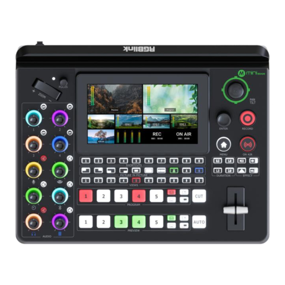
Page 14: Front Panel
● PROGRAM FTB Button ● PREVIEW Source Row ● Volume Control Knob ● PREVIEW Layer Button ● AFV Button ● PREVIEW Clear Button ● Mute Button © Xiamen RGBlink Science & Technology Co., Ltd. | support@rgblink.com | www.rgblink.com Ph: +86 592 5771197... - Page 15 ○ to accept the selected item or apply changes to a setting. ○ to edit. ○ to enter the next higher level of menu. ○ to enable or disable a function. © Xiamen RGBlink Science & Technology Co., Ltd. | support@rgblink.com | www.rgblink.com Ph: +86 592 5771197...
- Page 16 ○ Rotate button for manual focus. ○ Press button for auto focus. █ Toggle ● Size adjustment for Layer A and Layer B. ● Zoom in/out for PTZ control. © Xiamen RGBlink Science & Technology Co., Ltd. | support@rgblink.com | www.rgblink.com Ph: +86 592 5771197...
- Page 17 ● Default: MIX. ● Button Lit White: selected transition effect. █ Transition Duration Selection Button ● Default: 1.0 second. ● Button Lit White: selected transition duration. © Xiamen RGBlink Science & Technology Co., Ltd. | support@rgblink.com | www.rgblink.com Ph: +86 592 5771197...
- Page 18 Preset Loading Button ● Button Color Description ○ Button Unlit: no view contained. ○ Button Lit Green: view contained. ○ Button Lit Red: view being loaded. © Xiamen RGBlink Science & Technology Co., Ltd. | support@rgblink.com | www.rgblink.com Ph: +86 592 5771197...
- Page 19 ○ Press Button Lit Red: to act in reverse from black to the currently selected source, and button goes dark. © Xiamen RGBlink Science & Technology Co., Ltd. | support@rgblink.com | www.rgblink.com Ph: +86 592 5771197...
- Page 20 ○ Short Press Button Unlit: to clear layer on PVW and save it to view. Button turns green. ○ Short Press Button with View: to load view to PVW. © Xiamen RGBlink Science & Technology Co., Ltd. | support@rgblink.com | www.rgblink.com Ph: +86 592 5771197...
-
Page 21: Dimension
1.2.4 Dimension Following is the dimension of mini-edge for your reference: 280mm x 220mm x 67mm © Xiamen RGBlink Science & Technology Co., Ltd. | support@rgblink.com | www.rgblink.com Ph: +86 592 5771197... -
Page 22: Chapter 2 Install Your Product
HDMI 1 automatically. Users can see the input views on the mini-edge screen when there is active signal plug in. Connect mini-edge to a monitor with HDMI output interface to see PVW views and output resolutions. -
Page 23: Connecting Microphone And External Monitoring Devices
6.35mm TRS jack, which can be directly connect to the mobile phone, computer and console. mini-edge comes with TWO audio output jacks on the right panel. One adopts 3.5mm mini-jack, which can be directly connect to the headphone for audio monitoring. The other line PGM output ©... -
Page 24: Connecting Usb For Streaming And Recording
6.35mm TRS jack, which is for connecting speakers. For laptops or mobile phones with no audio output ports, mini-edge provides a built-in Bluetooth module. Users can connect to devices with Bluetooth function to input high-quality audio signals in real time. (More details please refer to Bluetooth) In addition, the four HDMI input ports all support embedded audio. -
Page 25: Connecting Router
Rotate ENTER Knob to move the cursor to SETTING > Push ENTER Knob > Rotate ENTER Knob to move the cursor to NETWORK >Turn OFF DHCP to set IP address. When connecting mini-edge and the router, the IP address of mini-edge must be in the same LAN as the router. 2.6 Plugging in Power RGBlink mini-edge is packaged with a PD power adapter (power cable included) , check the power supply standard used in your country or region before power connection. -
Page 26: Turning On Your Mini-Edge
3. The power supply is rated for a minimum of 36W. 2.7 Turning on Your mini-edge After mini-edge is connected to power supply, push the DIP Switch on the rear panel, the device will show mini-edge logo and then enter to the main interface. -
Page 27: Chapter 3 Use Your Product
After the above steps are completed, users can use mini-edge to do the following. 3.1 Main Interface As shown below, once powering on mini-edge, the 5.5 inch display will show mini-edge logo and then come into Main Interface. Operator can refer to the description below. -
Page 28: Menu
Push MENU Button in Main Interface and the LCD screen will quickly enter MENU. As shown in the figure above, the UI style on thescreen is similar to current smart phone © Xiamen RGBlink Science & Technology Co., Ltd. | support@rgblink.com | www.rgblink.com... -
Page 29: Standby Interface
Rotate ENTER knob to move the cursor to icon to enter Standby Interface. ❶ ❷ ❻ ❸ ❹ ❺ Area Description ❶ PREVIEW Show Preview screen and audio meter. © Xiamen RGBlink Science & Technology Co., Ltd. | support@rgblink.com | www.rgblink.com Ph: +86 592 5771197... -
Page 30: Pip (Picture-In-Picture)
Media Management Interface. 3.4 PIP (Picture-in-Picture) mini-edge defaults to single-screen switching. If you need to use PIP, push MENU Button to enter MENU, use ENTER knob to move the cursor to LAYOUT icon, then press ENTER knob once again to gain access to the PIP layout setting interface. - Page 31 PIP video source will be displayed in the PGM window as an inset window. RGBlink offers 6 layout options. If the Layout【6】 is selected, use the Toggle to achieve a better view of the picture ratio.
-
Page 32: Adding Layers
1. Insert a U disk into USB interface labeled number 1, reboot mini-edge or enter BACKGROUND/LOGO/OVERLAY interface. 2. Wait for mini-edge to recognize available files. Figure below indicates no files available in U disk. © Xiamen RGBlink Science & Technology Co., Ltd. - Page 33 3. If there are no available files, the USB flash drive will automatically create a folder named mini-edge , with audio, image, video folders included. The image folder includes three sub-folders: background, logo and overlay. Tips: Layers should meet the following requirements: 1.
-
Page 34: Adding Background
1. Create a folder name mini-edge by yourself. 2. Create audio, image, video folders respectively in mini-edge folder. 3. Create three sub-folders in image: background, logo and overlay. 4. Store materials in corresponding folder. Tips: RGBlink website ( https://rgblink-web.azurewebsites.net/productsinfo.aspx?id=252) >... - Page 35 Program screen and the button will be illuminated red. Press button illuminated red to remove, and the button indicator changes to white. © Xiamen RGBlink Science & Technology Co., Ltd. | support@rgblink.com | www.rgblink.com Ph: +86 592 5771197...
-
Page 36: Adding Layer A
3. Use the toggle on the control panel for layer zoom-in and zoom-out and the joystick to set the position for more detailed adjustment. © Xiamen RGBlink Science & Technology Co., Ltd. | support@rgblink.com | www.rgblink.com Ph: +86 592 5771197... -
Page 37: Adding Layer B
Layer A and place it on the background. 3.5.4 Adding Layer B 1. Push Layer B Button on the front panel to edit Layer B. This operation simultaneously enables Layer B. © Xiamen RGBlink Science & Technology Co., Ltd. | support@rgblink.com | www.rgblink.com Ph: +86 592 5771197... -
Page 38: Adding Logo
3. Layout Selection, Size & Position Adjustment, Layer Cropping & Scaling, please refer to operations in Adding Layer 3.5.5 Adding LOGO 1. Insert a U disk into the USB port labeled number 1 to import LOGO sources. © Xiamen RGBlink Science & Technology Co., Ltd. | support@rgblink.com | www.rgblink.com Ph: +86 592 5771197... -
Page 39: Adding Overlay
Red. Press button illuminated red to remove, and the button indicator changes to white. 3.5.6 Adding Overlay Insert a U disk into the USB port labeled number 1 to import overlay sources. © Xiamen RGBlink Science & Technology Co., Ltd. | support@rgblink.com | www.rgblink.com Ph: +86 592 5771197... - Page 40 Choose overlay source in U disk and then tap "+" to add it to Source Selection Area. Long press the added source for deletion. Push Overlay Button on the front panel to enable the function. © Xiamen RGBlink Science & Technology Co., Ltd. | support@rgblink.com | www.rgblink.com Ph: +86 592 5771197...
-
Page 41: Chroma Key
Joystick to quickly adjust horizontal and vertical position of OVERLAY. 3.6 Chroma Key mini-edge supports matting, that is, removing the pure color background and overlaying it on another signal to realize the application of virtual reality. Push MENU Button to enter Main Menu, tap【CHROMA KEY】in MENU or push Button 5 to enter the setting interface. -
Page 42: Controlling Ptz Camera
IP VISCA protocol and save the position and zoom information for quick calling. The PTZ preset of mini-edge not only saves the parameters of the PTZ, but also includes calling the camera, that is, when the preset of PTZ is loaded, the input is switched to the camera signal source at the same time. - Page 43 FAQ. 2) Enter PTZ configuration interface below to set the camera's IP address, then click "Enter" to save. (Make sure IP address has not been occupies, and IP address of mini-edge and camera are in the same LAN.) ©...
- Page 44 3) Connect camera and computer to the switch. 4) Connect mini-edge and camera to the switch via Ethernet cables (It is recommended to use RGBlink CAT6 cable with order code as 940-0001-00-11-0). Then use mini-edge for PTZ control. Warning: 1. The computer IP, mini-edge IP and the tested IP must be in the same LAN.
- Page 45 Users can create multiple views by setting different camera presets and adjusting parameters such as zoom. Choose to capture a picture and add it to View. © Xiamen RGBlink Science & Technology Co., Ltd. | support@rgblink.com | www.rgblink.com Ph: +86 592 5771197...
-
Page 46: Saving And Loading Scenes
3.8 Saving and Loading Scenes mini-edge save presets to Scene in real time. If users want to quickly load current preset next time, just save it to corresponding scene. The Scene will save all the currently set parameters including Chroma Key, PTZ Presets and more. -
Page 47: Video Output
The preset saving interface is shown as below. mini-edge allows user to save 10 presets in total to the corresponding View 1~10. If the selected window does not contain a preset, press ENTER knob to choose whether to form a static picture of the current scene and save it. -
Page 48: Multi-View
HDMI is generally used to adapt displays with HDMI input interfaces. Turn on DVI/HDMI, mini-edge can adapt to different types of display devices. Users can return to Editing Interface to check input source preview on the touch screen. -
Page 49: Resolution
Choose USB2 Mode to set the function of USB-C interface labeled number 2. ● UVC Output: USB port can be recognized as USB webcam to connect computer or mobile phone for streaming or video conference. © Xiamen RGBlink Science & Technology Co., Ltd. | support@rgblink.com | www.rgblink.com Ph: +86 592 5771197... -
Page 50: Streaming
You can provide network for mini-edge through Direct Connection or Smartphone Tethering. 3.10.1 Direct Connection mini-edge switcher ’ s Ethernet connector lets you stream directly. Connect mini-edge to the © Xiamen RGBlink Science & Technology Co., Ltd. | support@rgblink.com | www.rgblink.com... -
Page 51: Smartphone Tethering
Ethernet port to an internet router or a network switch. It is recommended to use RGBlink CAT6 cable with order code as 940-0001-00-11-0. 3.10.2 Smartphone Tethering 1. For iOS system, please do as follows: 1) Simply connect a standard power cord from your smartphone to the USB-C port labeled number 1 on your mini-edge. - Page 52 4) As shown in figures below, if the status changes from "Not Discoverable" to "Connection", it means that the mini-edge and your mobile phone have achieved network sharing. 2. For Android system, please do as follows: 1) Open ‘Settings’> ‘Additional settings’> ‘Developer options”> Turn on ‘USB debugging’.
- Page 53 4) Select SETTING in MENU to enter following interface. You can also access to Setting Interface by choosing icon. Choose Network in Setting and then Mobile to stream by using the hotspot of mobile phone. © Xiamen RGBlink Science & Technology Co., Ltd. | support@rgblink.com | www.rgblink.com Ph: +86 592 5771197...
-
Page 54: Youtube Live
2. If failed to use network sharing, please operate Step 2 as follows: Connect USB-C interface of OTG cable to mini-edge, then use standard data cable to connect your phone to USB-A interface of OTG cable. 3. The user interface may vary according to mobile phone types, please refer to the actual use. - Page 55 6. Paste the Stream URL and Stream Key in notepad and save file title as rtmp.ini (the format must be : rtmp://YOUR STREAM URL/YOUR STREAM KEY). Then copy the file to USB disk. 7. Connect the USB disk to mini-edge’s USB port. As shown in the figure below, users can view the imported streaming address and streaming status.
-
Page 56: Controlling Ptz Camera During Live
To control PTZ camera while performing live streaming, please make sure PTZ, mini-edge and network are in the same LAN, then turn on DHCP of mini-edge in Network Interface at the same time. ( Turning off DHCP will not affect live streaming if the IP address does not conflict) Click Network on Setting Menu to configure IP address. -
Page 57: Recording
Subnet mask: Set the subnet mask. The default setting is 255.255.255.0. Gateway: Set the Gateway according to the IP address and subnet mask. For example, if the IP address of mini-edge is 192.168.5.98 and the subnet mask is 255.255.255.0, please set the gateway to 192.168.5.1. - Page 58 Insert a U disk to USB port labeled number 1. Before recording, format the U-disk first. You can directly format U-disk on your mini-edge. The steps are as below: Push MENU Button to enter Menu Choose 【 OUTPUT 】 in MENU to enter Video Output interface, then choose Record to enter recording configuration interface.
-
Page 59: Switch Effect Setting
Warning: If the U disk cannot be recognized when inserting into mini-edge, use a dual USB cable to power U disk. In Recording interface, the disk information can be captured automatically by mini-edge. Enable Recording switch to start or stop recording, and you can check recording duration and progress. -
Page 60: Audio
3.13 Audio mini-edge supports mixed output of multiple channels, and also allows user to check volume meter. Push MENU Button to enter MENU. Select 【AUDIO】 to enter the Audio Management Interface. As shown in the figure below, the Audio Management Interface is divided into eight parts. Please refer to the following table for operation. - Page 61 ● Set AFV for any HDMI embedded audio so the audio switches with the video source to © Xiamen RGBlink Science & Technology Co., Ltd. | support@rgblink.com | www.rgblink.com Ph: +86 592 5771197...
- Page 62 If the sound is too quiet or too loud, you need to control audio level. Tap MIC 1, MIC 2, Line-in input icon to set audio levels for microphone in different types. © Xiamen RGBlink Science & Technology Co., Ltd. | support@rgblink.com | www.rgblink.com...
-
Page 63: Setting
Display. 3.14.1 About Choose About to check information about mini-edge. As shown in the figure below, users can view Device Name and SN serial number. Select Device Version to check current version and © Xiamen RGBlink Science & Technology Co., Ltd. -
Page 64: Date And Time
Upgrade) 3.14.2 Date and Time Choose Date & Time to check operating time and set time displayed in mini-edge. If the device is connected to network, turn on automatic setting switch to synchronize the time. -
Page 65: Language
3.14.4 Bluetooth Choose Bluetooth to enter the following interface. Bluetooth defaults to ON. Turn on Bluetooth on mini-edge and mobile phone to establish a Bluetooth connection. You can check device name in this interface and then select the mini-edge model that needs to be paired in the Bluetooth Setting Interface of the phone. -
Page 66: Views Auto Loop
After successful connection of mini-edge and mobile phone, you can play music via Bluetooth. Tips: 1. mini-edge is generally named as mini-edge-XXXX. 2. If there is no sound when playing music, please use the Channel Fader on the front panel to adjust the BLUETOOTH and PREVIEW volume to an appropriate level. -
Page 67: Reset
T-Bar Mode. Users can also switch to CUT Mode and then use Button 1~5 on the operation board to switch inputs. For some important occasions, users might need to preview and preset the next scene to ensure the accuracy and stability of the screen. -
Page 68: Auto Return
3.14.10 Display Select Display to enter the interface below. Use ENTER knob or adjuster to control brightness of touch screen and buttons. © Xiamen RGBlink Science & Technology Co., Ltd. | support@rgblink.com | www.rgblink.com Ph: +86 592 5771197... - Page 69 In addition to above settings, users can also set Chinese or English as the interface language. © Xiamen RGBlink Science & Technology Co., Ltd. | support@rgblink.com | www.rgblink.com Ph: +86 592 5771197...
-
Page 70: Chapter 4 Ordering Codes
Chapter 4 Ordering Codes 4.1 Product Code 230-0006-01-0 mini-edge © Xiamen RGBlink Science & Technology Co., Ltd. | support@rgblink.com | www.rgblink.com Ph: +86 592 5771197... -
Page 71: Chapter 5 Appendix
Linear PCM, 16 bits/48 kHz, 2 ch Record/Storage Record Formats MP4 | WAV Disk Formats FAT32( ≤ 32 GB) | exFAT(64GB~2T) Supported Standards HDMI H.265 ITU-T H.265/ ISO/IEC 23008-2 © Xiamen RGBlink Science & Technology Co., Ltd. | support@rgblink.com | www.rgblink.com Ph: +86 592 5771197... -
Page 72: Faq
5.2 FAQ 1. Fail to power on mini-edge? A: The Power Supply included with mini-edge is the recommended power supply to use. If you use other power supply, make sure the power supports 12V 3A. Then check whether the power supply is connected first, and use it correctly according to the power supply standard of your country/region. - Page 73 For example, the IP address of PTZ is 192.168.5.163. Please also set the IP address of mini-edge to 192.168.5.X ( (2~254) except163 Outside), confirm on mini XPOSE whether the Visca port number in the PTZ settings is the corresponding port number, for example, the Visca port number of the PTZ of RGBlink is 1259.
- Page 74 8. mini-edge HDMI input what kind of YUV. A:mini-edge supports 4:4:4,not supports 4:2:0. 9. When mini-edge input is i format signal will be half-screened or cut with the P format signal, the height of the P format will be cut.
- Page 75 "Destination host unreachable," it means that the IP has not been occupied. 12.4) Then enter "ping 192.168.5.66" in the "Run" dialog box again. Press "Enter" on the keyboard to access this IP address. © Xiamen RGBlink Science & Technology Co., Ltd. | support@rgblink.com | www.rgblink.com Ph: +86 592 5771197...
-
Page 76: Upgrade
2) Dropbox https://www.dropbox.com/scl/fo/07xkx4n6fcixm816v2yxq/h?rlkey=9qtaewha08wb2n1wqhbue63 mn&dl=0 Warning: Do not power off during the upgrade process, otherwise mini-edge may be unable to enter the system after booting. Steps: 1.Copy upgrade package to root directory of USB disk. 2.Power on the device and connect USB disk to USB-C port labeled number 1 by an OTG cable. - Page 77 USB disk; choose【Upgrade】to upgrade mini-edge: 5. The upgrade interface is shown in the figure below. Please DO NOT power off the device during upgrade. mini-edge will reboot after upgrade is completed. © Xiamen RGBlink Science & Technology Co., Ltd. | support@rgblink.com | www.rgblink.com...
-
Page 78: Terms & Definitions
8 channels of audio, and control signals, over a single cable. ● HDMI 1.3: Released on June 22 2006, and increased the maximum TMDS clock to 340 MHz (10.2 Gbit/s). © Xiamen RGBlink Science & Technology Co., Ltd. | support@rgblink.com | www.rgblink.com... - Page 79 ●Single-mode Fiber: Fiber that support a single mode are called single-mode fibers. Single-mode fibers are used for most communication links longer than 1,000 meters (3,300 ft). © Xiamen RGBlink Science & Technology Co., Ltd. | support@rgblink.com | www.rgblink.com Ph: +86 592 5771197...
- Page 80 3.2 Gen 2x2 (original name USB 3.2) with speed up to 5Gbps,10Gbps,20Gbps respectively. USB version and connectors figure: Type Type B Mini Mini Micro- Micro Type C USB 2.0 USB 3.0 © Xiamen RGBlink Science & Technology Co., Ltd. | support@rgblink.com | www.rgblink.com Ph: +86 592 5771197...
- Page 81 TCP (UDP) Ethernet based © Xiamen RGBlink Science & Technology Co., Ltd. | support@rgblink.com | www.rgblink.com...
- Page 82 As with XML and JSON, the OSC protocol allows sharing data. OSC is transported via UDP packets between devices connected on an Ethernet. © Xiamen RGBlink Science & Technology Co., Ltd. | support@rgblink.com | www.rgblink.com...
- Page 83 ●Seamless Switching: A feature found on many video switchers. This feature causes the switcher to wait until the vertical interval to switch. This avoids a glitch (temporary scrambling) which often is seen when switching between © Xiamen RGBlink Science & Technology Co., Ltd. | support@rgblink.com | www.rgblink.com...
-
Page 84: Revision History
Release Aster All information herein is Xiamen RGBlink Science & Technology Co Ltd. excepting noted. is a registered trademark of Xiamen RGBlink Science & Technology Co Ltd. While all efforts are made for accuracy at time of printing, we reserve the right to alter otherwise make change without notice. -
Page 85: Chapter 6 Support
Chapter 6 Support © Xiamen RGBlink Science & Technology Co., Ltd. | support@rgblink.com | www.rgblink.com Ph: +86 592 5771197... - Page 86 © Xiamen RGBlink Science & Technology Co., Ltd. | support@rgblink.com | www.rgblink.com Ph: +86 592 5771197...
Need help?
Do you have a question about the mini-edge and is the answer not in the manual?
Questions and answers