
Related Manuals for WATSON Edison Workbench Extended Connector


Summary of Contents for WATSON Edison Workbench Extended Connector
- Page 1 ASSEMBLY Edison Workbench Extended Connector V.21.0 12/2023 360.394.1300 watsonfurniture.com...
- Page 2 Important Safety Instructions This product is for commercial use only. Maximum intended load for each worksurface is 200 lbs (91 kg) When using an electrical furnishing, basic precautions should always be followed, including the following: Read all instructions before using (this furnishing). DANGER To reduce the risk of electric shock: 1.
- Page 3 12. Electrical connection between rail segments shall be disconnected prior to removal of a mechanical connection. 13. The system may be supplied by a three phase power system with four individual circuits rated at 20 amps/120 volts max-imum, or as permitted by local code. 14.
- Page 4 Tools Socket Extension 6mm Socket Socket Wrench Hardware M6 Nut (490611) Essential Components Extended Connector...
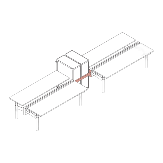
- Page 5 Align Extended Connector Align one end of the Extended Connector to the end of the Edison Workbench Beam (1a). Slide the two threaded PEM studs into the diamond shape hole features and secure using two (2) M6 Nuts (1b). Note: If an end cover is in place on the end of the Beam, remove it and put it aside.
- Page 6 Replace Beam Side Panels Replace Beam Side Panels by aligning clearace cuts with curved H-Leg bar and magnets on the Beam. Note: Worksurface Tops removed from illustration for clarity.
- Page 7 Position Storage units Position Storage units in between Bench segments and against the Extended Connector. Be sure to leave approximately 2 inches of clearance between Edison Workbench tops and Storage Units to prevent pinch point injury.
Need help?
Do you have a question about the Edison Workbench Extended Connector and is the answer not in the manual?
Questions and answers