Advertisement
Quick Links
Advertisement

Subscribe to Our Youtube Channel
Related Manuals for WATSON Edison Workbench


Summary of Contents for WATSON Edison Workbench
- Page 1 ASSEMBLY Edison Workbench V.21.0 12/2023 360.394.1300 watsonfurniture.com...
-
Page 2: Important Safety Instructions
Important Safety Instructions This product is for commercial use only. Maximum intended load for each worksurface is 200 lbs (91 kg) When using an electrical furnishing, basic precautions should always be followed, including the following: Read all instructions before using (this furnishing). DANGER To reduce the risk of electric shock: 1. - Page 3 12. Electrical connection between rail segments shall be disconnected prior to removal of a mechanical connection. 13. The system may be supplied by a three phase power system with four individual circuits rated at 20 amps/120 volts max-imum, or as permitted by local code. 14.
- Page 4 Tools Additional tools such as a 90 Degree Bit and an 18” Extension are helpful for some steps. *No torque or ball bits should be used Phillips Drill/ 3mm Hex Drill/ 4mm Hex Drill/ 90 DGREE BIT Electric Drill Driver Bit Driver Bit Driver Bit 18”...
-
Page 5: Essential Components
Essential Components Rectangle Surface Super Ellipse Surface Modesty Side Panel Support Rail Power Beam Power Supply Cover End Plate Control Box Finishing Ring Switch Li ing Column Wire Manager Clip Coat Hook Energy Chain Bracket Energy Chain (Optional) (Optional) - Page 6 Essential Components (continued) Jumper Power Infeed Power Harness Dual Sided Height Dual Sided Fixed Single Sided Height Adjustable Adjustable Leg Assembly Height Leg Assembly Le Hand Leg Assembly Single Sided Height Adjustable Single Sided Height Adjustable Single Sided Height Adjustable Right Hand Leg Assembly Le Hand Leg Assembly Right Hand Leg Assembly...
- Page 7 Secure Power Duplexes. Place Power Beam sitting upright. Place the appropriate Power Duplex Module (single sided vs dual sided, two duplexes per side vs four duplexes per side) into the notch cuts in the center of the Power Beam (1a). Place the appropriately sized Power Supply Cover over the top of the power duplexes (1b).
- Page 8 Attach H-Legs to Power Beam. Flip the Power Beam so that its underside is facing upwards. Place each H-leg and Lifting Column Assembly into the notch in the underside of the Power Beam with the Lifting Columns pointing towards the center of the Beam (2a).
- Page 9 Attach Support Rail to Lifting Columns. Flip the Power Beam and H-leg assembly upright. Align each Support Rail over the top each Lifting Column (3a). Secure each Support Rail to each Lifting Column using four (4) M6x12mm Flat Head Screws per Lifting Column (3b). M6x12mm Flat Head Screw (0002637)
- Page 10 Secure Multiple Bench Segments. If ganging together multiple Single or Double Sided Bench Segments, place the Segments upright and end-to-end at the Power Beam End Bracket 4a). Insert two (2) Carriage Bolts through the diamond shaped cutout, passing through both Bench Segments, and secure each using a M6 Hex Nut (4b).
- Page 11 Install Jumpers/Infeed. Align Power Harness Outlets with cutouts in the Rail Segment. Feed the infeed through the cutout in the bottom of the appropriate Rail Segment. Note: Infeed can go into any of the cutouts in the rail segment to power up a rail.
- Page 12 Install Jumpers/Infeed. Once your Infeed is fed through the cutout in the bottom of the appropriate Rail Segment, connect it to the Power Harness (6a). Connect each end of a Jumper to an end of the Power Harness from both bench segments (6b). Note: Jumpers only connect in one orientation: arrows on Jumper and Harness will align to indicate proper connection.
- Page 13 Install End Plates. Align an End Plate to the outer ends of the Workbench (7a). Place the two (2) threaded studs on each End Plate through the two (2) diamond cutouts on each End Bracket of the Power Beam. Secure each End Plate using two (2) M6 Hex Nuts (7b). M6 Nut (490611)
- Page 14 Attach Perforated Panels to Power Beam. Secure the appropriately Perforated or Solid Side Panels to both sides of the Power Beam, making sure to locate the cutouts in front of the power duplexes. These panels will secure to the pre-installed magnets on the power beam.
- Page 15 Attach Control Box. Place each Control Box into Support Rail (9a). Secure each Control Box using two (2) M5 x 35mm Button Head Screws and two (2) M5 Weld Nuts (9b). Connect the closer of the two Lifting Columns directly to the Control Box and connect the other with a Power Cable. Plug in the Power Supply Cable and plug into the Power Beam.
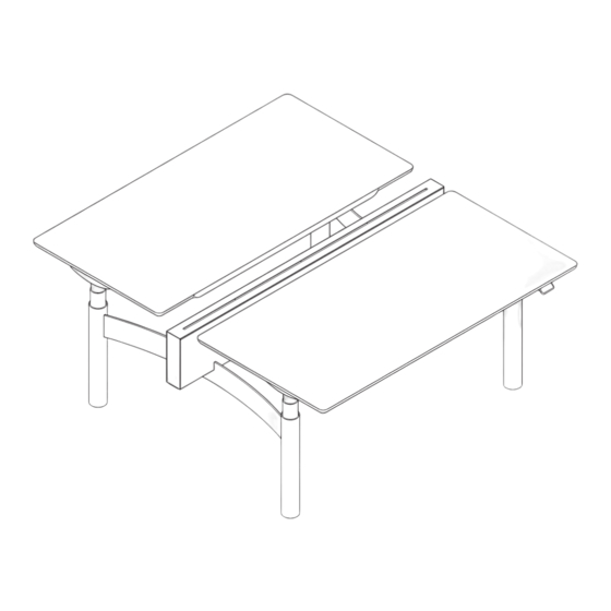
- Page 16 Secure Worksurface to Support Rail. Place the appropriately sized worksurface on top of each support rail with the switch facing outwards toward the user (10a). Align the mounting locations in the Support Rail with the Brass Inserts in the underside of the Top. Secure each worksurface to the Support Rail using eight (8) M6x12mm Button Head Screws (10b).
- Page 17 Secure Switch and Coat Hook. Align each Paddle Switch with pilot holes (11a). Secure each Paddle Switch using two (2) #8 x 3/4” Phillips Flat Head Screws per Switch (11b). Align Coat hook with pilot holes (11c). Secure each Coat hook using two (2) #8 x 3/4” Phillips Flat Head Screws per Hook (11d).” #8 x 3/4”...
- Page 18 Secure Wire Managers Clips. Align each Wire Manager Clip with each pilot hole (12a). Secure each Wire Manager Clip using one (1) #10 x 5/6” Truss Head Screw (12b). #10 x 5/6” Truss Head Screw (122800)
- Page 19 Secure Energy Chain (optional) If the workbench is height adjustable, secure the each Energy Chain Bracket to both ends of the Energy Chain. Secure one bracket to the pilot holes in the worksurface using two (2) #10 x 5/6” Truss Head Screws (13b) and the other to the underside of the power beam with two (2) M6-1.0 X 12MM Button Head Screws (13b).
Need help?
Do you have a question about the Edison Workbench and is the answer not in the manual?
Questions and answers