
Subscribe to Our Youtube Channel
Related Manuals for WATSON Edison Workbench Power Pole


Summary of Contents for WATSON Edison Workbench Power Pole
- Page 1 ASSEMBLY Edison Workbench Power Pole V.21.0 12/2023 360.394.1300 watsonfurniture.com...
-
Page 2: Important Safety Instructions
Important Safety Instructions This product is for commercial use only. Maximum intended load for each worksurface is 200 lbs (91 kg) When using an electrical furnishing, basic precautions should always be followed, including the following: Read all instructions before using (this furnishing). DANGER To reduce the risk of electric shock: 1. - Page 3 If Using Optional Utility Power - 1. The electrical desk plug must be plugged into the utility power when present. 2. This product is for use on a nominal 120-volt circuit and has a grounding plug that looks like the plug illustrated in sketch A (see Figure 77.1).
-
Page 4: Essential Components
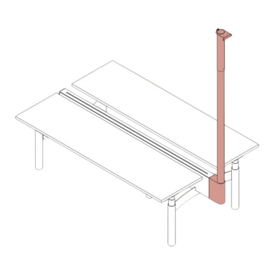
Hardware Straight Screen M6x12mm Bu on M4 Thread M6-1.0x12mm Low Head Screw Cu ing Screw Profile Cap Screw (125290) (121538) (0001140) Essential Components Power Pole Cover... - Page 5 Align Power Pole. Align the Power Pole with the corresponding holes in the Bench segment. Secure Power Pole. Secure the Power Pole to the Bench Beam using four (4) M6 x 12mm screws. M6x12mm Bu on Head Screw (125290)
- Page 6 Attach Clamp to Ceiling Bar. Hook the Ceiling Bar Clamp into the slots at the end of the Ceiling Bar and rotate into place, as shown below. Mount Ceiling Bar to Ceiling. Hook the Ceiling Bar on the 2’ ceiling grid and screw the Clamp to the Ceiling Bars with one (1) M6-1.0 x 12mm Low Profile Cap Screw on each side.
- Page 7 Connect Power Pole to Ceiling. Hook the Power Pole onto the Ceiling Bar, and align the Power Pole with the Bracket at the desired position. Fas- ten the Power Pole to the Ceiling Bar using four (4) M6-1.0 x 12mm Low Profile Cap Screws. M6-1.0x12mm Low Profile Cap Screw (0001140)
-
Page 8: Route Cables
Route Cables. Run the Cables down from the ceiling through the Power Pole (6a) and through the Bench Beam end (6b). Continue to run cables as required. Next feed connect Jumper to each end of each Power Harness (6c). Note: Illustration is a suggestion. You may configure your Jumpers as needed. -
Page 9: Attach Cover
Attach Cover. Slide the Cover onto the Power Pole from the outside (7a). and secure using one (1 M4 thread cutting screw (7b). M4 Thread Cu ing Screw (121538)
Need help?
Do you have a question about the Edison Workbench Power Pole and is the answer not in the manual?
Questions and answers