
Related Manuals for WATSON Edison Workbench Straight & Corner Screen


Summary of Contents for WATSON Edison Workbench Straight & Corner Screen
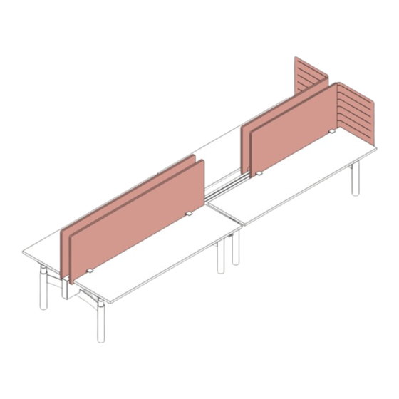
- Page 1 ASSEMBLY Edison Workbench Straight & Corner Screen V.21.0 12/2023 360.394.1300 watsonfurniture.com...
-
Page 2: Important Safety Instructions
Important Safety Instructions This product is for commercial use only. Maximum intended load for each worksurface is 200 lbs (91 kg) When using an electrical furnishing, basic precautions should always be followed, including the following: Read all instructions before using (this furnishing). DANGER To reduce the risk of electric shock: 1. - Page 3 If Using Optional Utility Power - 1. The electrical desk plug must be plugged into the utility power when present. 2. This product is for use on a nominal 120-volt circuit and has a grounding plug that looks like the plug illustrated in sketch A (see Figure 77.1).
-
Page 4: Essential Components
Hardware Straight Screen (0000229) (0000238) (125285 Black) Glide 5/16-18 x 1” #8 x 1-3/4” Square Drive (125290 Silver) Screw Slot Thread Cu ing Screw M6-1.00 x 12MM Bu on Head Screw Corner Screen (0000229) (0000238) (122800) Glide 5/16-18 x 1” #8 x 1-3/4”... - Page 5 Straight Screen Insert Clamping Glides into Mounting Brackets. Place each Clamping Glide into threaded hole in each Mounting Bracket as shown (1a). Tighten each Clamping Glide by turning clock-wise (1b). Position the head of the Clamping Glide at least 1-1/8” from the top of the Mounting Bracket (1c).
-
Page 6: Side View
Align Desk Screen to Worksurface. Align Straight Screen and Mounting Brackets to worksurface making sure Mounting Brackets are secured. Side View Attach Straight Screen to Worksurface. Using a flathead screwdriver, tighten each Clamping Glide by turning clock-wise (4a). If the Bench has a profile or Knife edge, secure with two (2) screws per Mounting Bracket (4b). - Page 7 Corner Screen Insert Clamping Glides into Mounting Brackets. Place each Clamping Glide into threaded hole in each Mounting Bracket as shown (1a). Tighten each Clamping Glide by turning clock-wise (1b). Position the head of the Clamping Glide at least 1-1/8” from the top of the Mounting Bracket (1c).
- Page 8 Secure Mounting Brackets to Worksurface. Using a flathead screwdriver, tighten each Clamping Glide by turning clock-wise (3a). If the Bench has a profile or Knife edge, secure with (2) screws per Mounting Bracket (3b). #8 x 1-3/4” Square Drive Thread Cu ing Screw (0000238) Align Corner Screen to Worksurface.
- Page 9 Insert the Medallion Bracket through the bottom slot in the metal portion of the Corner Screen and align it with the rear edge of the worksurface support rail. Secure the medallion. Secure the Medallion Bracket in place using two (2) screws. Repeat steps 1 thru 5 (Corner Screens) to install remaining Corner Screen.
Need help?
Do you have a question about the Edison Workbench Straight & Corner Screen and is the answer not in the manual?
Questions and answers