Table of Contents
Advertisement
Quick Links
Fike Suppression System ARM Manual / Recertification
As most have you have seen from recent training and/or the recertification binders, we updated the 06-106 ARM III
manual with old technical bulletin information and warnings.
This bulletin is issued to provide each Suppression distributor a copy of this revised ARM III manual and to remind
you that the 2005 recertification period is coming to a close. Each distributor that has attended a training class in
2003 forward (or recertified in 2003) is eligible to recertify this year. If recertification is not performed, you are
required to attend a new training class to maintain active certification.
12/13/05 ⋅ SDC 05-004
Page 1 of 1
th
Street ⋅ P.O. Box 610 ⋅ Blue Springs, Missouri 64013-0610 U.S.A. ⋅ (816) 229-3405 ⋅ (816) 229-0314 ⋅ www.fike.com
704 S. 10
Advertisement
Table of Contents

Subscribe to Our Youtube Channel
Summary of Contents for Fike ARM III
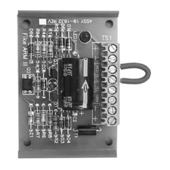
- Page 1 This bulletin is issued to provide each Suppression distributor a copy of this revised ARM III manual and to remind you that the 2005 recertification period is coming to a close. Each distributor that has attended a training class in 2003 forward (or recertified in 2003) is eligible to recertify this year.
- Page 3 ARM III Agent Releasing Module P/N: 10-1832 Installation, Operation and Maintenance Manual Manual P/N 06-106 Rev. No: 1, 07/03...
- Page 4 No part of this Fike Corporation cannot be held liable for any product may be copied, reproduced or transmitted damages resulting from the use or misuse of this by any mechanical, photographic, electronic or product.
- Page 5 Caution category. These notes can be of great benefit to the user and should be read. Tips – Tips provide advice that may save time during a procedure, or help to clarify an issue. Tips may include additional reference. 07/03 ARM III Installation Manual -ii- P/N 06-106 Rev. 1...
-
Page 6: Table Of Contents
WIRING INSTALLATION......................... 3 TESTING ARM'S ............................. 4 MAINTENANCE............................4 ........................4 OMPONENT REPLACEMENT ARMING THE SYSTEM........................... 5 DISARMING THE SYSTEM........................5 List of Exhibits 1-1 10-1832 ARM III M ........................1 XHIBIT ODULE 2-1 C ....................... 1 XHIBIT OMPATIBLE ELEASING EVICES 4-1 ARM 4"... - Page 7 FIKE CORPORATION This page intentionally left blank 07/03 ARM III Installation Manual -iv- P/N 06-106 Rev. 1...
-
Page 8: Introduction
INTRODUCTION COMPATIBILITY The ARM can be used in conjunction with the The Agent Release Module III (ARM III), Fike P/N releasing panels and devices indicated in Exhibit 10-1832, is used to interface between supervised 2-1. The maximum number of ARM's that can be... -
Page 9: Hardware Installation
Secure the ARM in the junction box using the lock fastener provided. Position any field wiring to relieve stress on the ARM. Do not install ARM Module on junction box lid. Exhibit 4-1 ARM 4" Square Mounting 07/03 ARM III Installation Manual P/N 06-106 Rev. 1... -
Page 10: Wiring Installation
ARM III Exhibit 5-2 Class B Wiring Exhibit 5-4 ARM PCB Initiator Releasing Circuit R B Y G R B Y G ARM III ARM III Exhibit 5-3 Class A Wiring 07/03 ARM III Installation Manual P/N 06-106 Rev. 1... -
Page 11: Testing Arm's
ARM to allow the system to reach Initiators should be replaced 5 years after normal state. manufactured date (each initiator is date coded). An AG1 flashbulb (Fike P/N 02-3799), electric match or the equivalent may be used to verify firing of the ARM. Potential danger... -
Page 12: Arming The System
The yellow and green terminals are shunted internally and connection to these Exhibit 7-1 ARM Shunt terminals provides safety for this pair (See Exhibit 7-1 below). GAS CARTRIDGE ACTUATOR LEADS SHUNTS 07/03 ARM III Installation Manual P/N 06-106 Rev. 1... - Page 13 704 South 10th Street P.O. Box 610 Blue Springs, Missouri U.S.A. 64013 (816) 229-3405 Fax: (816) 229-0314 www.fike.com...


Need help?
Do you have a question about the ARM III and is the answer not in the manual?
Questions and answers