
Subscribe to Our Youtube Channel
Related Manuals for Fike MICROMIST 10-2340


Summary of Contents for Fike MICROMIST 10-2340
- Page 1 MICROMIST INTERFACE MODULE User’s Guide PART NUMBER 10-2340 Manual P/N: 06-218 Rev 1, 06/01...
- Page 3 The information contained in this manual is as accurate as currently possible. This manual is intended to be an aid to Fike authorized distributors, who have been trained in an approved manner by Fike, and the user who is a customer of the Fike authorized distributor. Fike does not warrant that this manual is technically correct, complete, or free from writing problems or that the Fike products referenced therein are free from minor flaws.
-
Page 5: Table Of Contents
FIKE CORPORATION TABLE OF CONTENTS Section Page PREFACE ...............................1 About this Manual ........................1 Product Support .........................1 Revision History .........................1 Terms Used in this Manual ......................1 Safety Notices ..........................2 PRODUCT OVERVIEW/EQUIPMENT ....................3 Listings and Approvals.......................3 Related Documentation ......................3 Product Description........................4 Part Numbers / Replacement Parts ...................5... - Page 6 This page intentionally left blank...
-
Page 7: Section Page
Fike Micromist Interface Module, Part Number 10-2340. The information contained in this manual must be utilized by an authorized distributor trained by Fike Corporation in order to properly install, test and service the Micromist Interface Module. This manual can also be used by the end user as an Operations Manual for the Micromist Interface Module. -
Page 8: Safety Notices
Always ground yourself with a proper wrist strap before handling the Interface module. If the installer is grounded at all times, damage due to static discharge will not occur. If the module requires repair or return to Fike, it must be shipped in an anti-static bag. -
Page 9: Product Overview/Equipment
ENV50141 immunity test 2.2 RELATED DOCUMENTATION To obtain a complete understanding of the Fike Micromist Interface Module or to become familiar with related functions in general, refer to the documentation listed in Table 2.2-1 below. Table 2.2-1 Fike Document Title... -
Page 10: Product Description
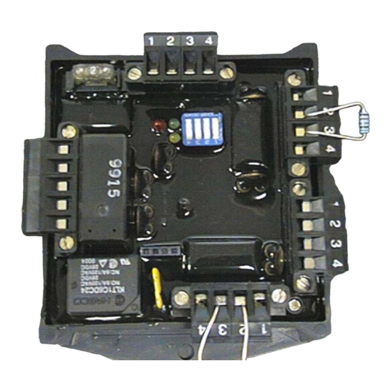
FIKE CORPORATION 2.3 PRODUCT DESCRIPTION The Fike Micromist Interface Module has five removable terminal blocks for wiring connections. The electronic module is encapsulated in a black 4” (101.6mm) square polycase enclosure. It contains a black test jack for testing and troubleshooting (power ground reference). Instant status of the module is available by observing the three color status LED’s. -
Page 11: Part Numbers / Replacement Parts
FIKE CORPORATION The following will describe each terminal block and it’s function. P1 - Power Input This circuit is for 24VDC power input. The terminal block is four positions; providing +/- inputs coming to the module and +/- going out of the module to the next device requiring 24VDC power as necessary. -
Page 12: Specifications
FIKE CORPORATION SPECIFICATIONS 20.0 – 30.0 Volts DC Supply Voltage P1 max. ripple under Normal State: 125mV peak to peak max. ripple under Alarm State: 500mV peak to peak Using 12Vdc 10Watt Solenoids (North America): Normal Standby: 0.080 amp Current Alarm: 1.000 amp... -
Page 13: Design
Service. The releasing circuit output of the control panel must be a contact closure type (relay) or 24VDC polarity reversal output. This module does not pause and re-check activation between cycles (as the Fike Cheetah panel does for Micromist releasing). All other limitations are listed in the Specifications, section 2.3 of this manual. - Page 14 FIKE CORPORATION This page intentionally left blank Page 8 of 17 Micromist Interface Module User Guide Rev. 1, 06/01 Manual P/N: 06-218...
-
Page 15: Installation Instructions
FIKE CORPORATION 4.0 INSTALLATION INSTRUCTIONS The Micromist Interface Module shall be mounted in a clean, dry environment free from debris. The enclosure selected to mount the Micromist Interface Module shall be suitable for the location of the installation. Do not attempt to install this device without reading all the instructions that follow. Failure to do so may result in damage to the device or accidental release of the associated Watermist Suppression system. -
Page 16: Wiring Diagrams
FIKE CORPORATION Wiring Diagrams 4.1.1 Micromist Interface Module initiation via contact closure input, with Class A contact monitoring. Page 10 of 17 Micromist Interface Module User Guide Rev. 1, 06/01 Manual P/N: 06-218... -
Page 17: Contact Closure Input, Class A
FIKE CORPORATION 4.1.2 Micromist Interface Module initiation via contact closure input, with Class B contact Monitoring. Micromist Interface Module User Guide Page 11 of 17 Manual P/N: 06-218 Rev. 1, 06/01... -
Page 18: Reverse Polarity Input, Disable Circuit Class B
FIKE CORPORATION 4.1.3 Micromist Interface Module initiation via polarity reversal input, with Class B contact monitoring of Disable input. Page 12 of 17 Micromist Interface Module User Guide Rev. 1, 06/01 Manual P/N: 06-218... -
Page 19: Reverse Polarity Input, Disable Circuit Class A
FIKE CORPORATION 4.1.4 Micromist Interface Module initiation via polarity reversal input, with Class A contact monitoring of Disable input. Micromist Interface Module User Guide Page 13 of 17 Manual P/N: 06-218 Rev. 1, 06/01... - Page 20 FIKE CORPORATION This page intentionally left blank Page 14 of 17 Micromist Interface Module User Guide Rev. 1, 06/01 Manual P/N: 06-218...
-
Page 21: Programming
FIKE CORPORATION PROGRAMMING Mode of Operation Switch Position 1 Switch Position 2 Switch Position 3 Switch Position 4 Continuous Output Turbine Generator Machinery Space *Note: All other combinations will result in an invalid configuration setting. While in an invalid configuration, the module will toggle between the normal and trouble states. -
Page 22: Acceptance Testing
If the device fails to operate as outlined in this manual, contact the installing distributor or call Fike’s Product Support Department at (816) 229-3405. If there is any doubt as to the functionality of the device, Fike recommends that you remove and replace the device. -
Page 23: Maintenance
Reference NFPA 72 and the specific control panel manual for proper maintenance schedules of the system. Only a qualified, factory trained Fike distributor should service this device. There are no user- serviceable parts on this device. Prior to performing scheduled maintenance and/or testing, the service technician must make sure... - Page 26 704 South 10 Street P.O. Box 610 Blue Springs, Missouri 64013 U.S.A. (816) 229-3405 Fax: (816) 229-5082 http://www.fike.com...
Need help?
Do you have a question about the MICROMIST 10-2340 and is the answer not in the manual?
Questions and answers