
Subscribe to Our Youtube Channel
Related Manuals for Fike FAV


Summary of Contents for Fike FAV
- Page 1 INSTALLATION AND MAINTENANCE INSTRUCTIONS Explosion Isolation Valve - FAV EXPLOSION PROTECTION SYSTEMS Doc. 8.8503.00.9 Rev. April, 2018 SOLUTIONS Fire Protection Explosion Protection Overpressure Protection Pressure Activation...
- Page 2 Fike products. Do not use any Fike products for any application for which it is not intended. Fike shall not be in any way liable for any damages or losses incurred by you or third parties arising from the use of any Fike product for which the product is not intended by Fike.
- Page 3 Valve Actuator Assembly Handling Warning....................14 6.2. FAV Maintenance ............................14 6.2.1. Actuating Cylinder Rebuild ......................... 14 6.2.2. Gate Damper Replacement (DN50 – DN200 FAV) ..................14 6.2.3. Gate Damper Replacement (DN250 – DN500 FAV) ..................15 6.3. Roll Pin Replacement ............................15 6.4.
- Page 4 The deflagration type of explosion is generally referred to as a combustion reaction where the flame front burns into the unburned material at a velocity lower than the speed of sound. The Fike hardware is designed to provide protection against deflagrations only, not against detonations unless otherwise specified.
- Page 5 The information contained in this document is provided for reference purposes only. For further product information or ordering replacement parts, please contact your local Fike Branch Office or Representative (details of which can be found on the back page) or Fike Product Support by calling 816-229-3405 (fax: 816-229-0314) or Fike Europe Product Support at +32 14 21 00 31 (fax: +32 14 21 07 43).
- Page 6 REFURBISH THE CONTAINERS. FIKE SHALL NOT BE LIABLE FOR CONSEQUENTIAL DAMAGES TO FIKE ASSEMBLIES, COMPONENT PARTS OR HARM TO PERSONNEL IF WORK TO THE FIKE EQUIPMENT IS CARRIED OUT BY NONE FIKE CERTIFIED ENGINEERS. THE SECTIONS MARKED WITH THIS ICON REQUIRE SPECIALIST ASSISTANCE. PLEASE CONTACT FIKE FOR INFORMATION, ASSISTANCE OR SERVICE TRAINING PROGRAMS.
- Page 7 The Fike Explosion Isolations Valves are designed to act upon the detection at the incipient stage of a combustion, and mechanically isolate the combustion. The system suitable for dust –air mixtures with a deflagration index or...
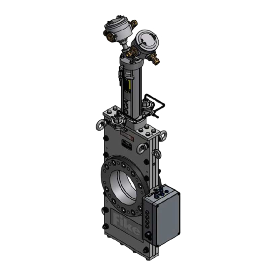
- Page 8 To identify the FAV and order replacement parts, the FAV and its driving container have been permanently labeled. The FAV is tagged with a name sticker (fig. 1). Figure 1 - Sticker Fast Acting Valve (FAV) The CE name plate on the valve body contains among other following information: Model, Serial No, Size and Date of Manuf.
- Page 9 Roll pin plug Gate damper Bottom cover plate Upper end cap Cylinder Lower end cap Flange FAV identification plate Figure 4 - FAV composing parts Doc. 8.8503.00.9 PAGE / 7 Rev. April, 2018...
- Page 10 Figure 5 - Dimensions Doc. 8.8503.00.9 PAGE / 8 Rev. April, 2018...
- Page 11 Table 2 - Dimensions different sizes FAV Valve ANSI Max. Valve Actuator bolting Bolt Weight torque Size Assembly diameter (mm) (mm) (mm) (mm) (mm) (mm) (kg) (Nm) Bolting 2” 5/8 –11 UNC 50.8 120.6 DN50 PN10/16 M16 x 2 50.8 120.6...
- Page 12 The device shall display a label marked “Approved device for measuring Valve Actuator Assembly continuity”. • If a Valve Actuator Assembly is suspected of being defective, contact Fike. Refer to the Repair and Return Authorization section of this document for the return procedure. •...
- Page 13 • During connection of the Valve Actuator Assembly to the terminal strip, the Valve Actuator Assembly shall remain shunted until all Valve Actuator Assemblies are connected to the appropriate terminals. The valve shall be positioned according to figure 6: The valve can be mounted from an upright vertical position to a horizontal position.
- Page 14 Figure 7 - Electrical scheme open/close module The magnetic switches detect the opening and close position of the magnetic ring which is connected on the piston. Hereby, the system (PLC) can check if the valve is open or close. Figure 8 - Position indicator piston Doc.
- Page 15 Step 2: Verify that the power is off at the control panel and all electrical charges have been dissipated. Step 3: Refer to the EPC Manual (doc. n° E06-051-X) for the remainder of this procedure. Also refer to Fike document X.2.26.01-x Valve Actuator Assembly.
- Page 16 Step 1: Remove the two (2) muffler assemblies from the base of the FAV actuating cylinder. Step 2: With the FAV in the closed position (down), remove the nuts and lock washers at the upper end of the actuating cylinder.
- Page 17 Step 2: With the slit of the new roll pin oriented to the top or bottom of the FAV, use a punch and hammer to insert it into the assembly. Replace the roll pin access plugs or covers.
- Page 18 Step 2: Place the original Shims on each Flange. Step 3: Assemble the Flanges to the FAV. Do not fully tighten the cap screws. Step 4: Align the bore of each flange with the bore of the gate and torque the cap screws in one-third increments in a crisscross fashion.
- Page 19 Doc. 8.8503.00.9 PAGE / 17 Rev. April, 2018...
- Page 20 • Cycle the gate in both directions ten (10) times, to insure free movement using shop air. • Inspect the Valve Actuator Assembly area for evidence of deterioration. • Refurbish the FAV system per specific instructions contained in this manual. • Replace the Valve Actuator Assembly.
- Page 21 The following procedure must only be performed by a Fike qualified Service Engineer, who has been assigned to prepare and complete the de-commissioning of the above referenced Explosion Protection System. Each step in the listed procedure must be adhered to and completion/acceptance of this form is mandatory. The Service Engineer must check off each of the following steps.
- Page 22 Any component that is to be returned to Fike must be approved for return prior to shipment. In order for the returned component to receive the correct attention ≈ credit ≈ repair ≈ replacement ≈ either under warranty or at the owner's expense, a Material Return Authorization number must be assigned by Fike.
- Page 24 CONTACT US Fike Europe Toekomstlaan 52 2200 Herentals, Belgium Tel: 0032 14 21 00 31 www.Fike.com For a list of contact information for Fike offices around the world, visit the Global Locations section of Fike.com...
Need help?
Do you have a question about the FAV and is the answer not in the manual?
Questions and answers