
Related Manuals for Fike Lantronix XPort 10-2627


Summary of Contents for Fike Lantronix XPort 10-2627
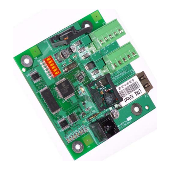
- Page 1 Ethernet Module (P/N 10-2627) Lantronix XPort Programming Guide Manual P/N: 06-388-1 Rev. No: 0, 09/08...
-
Page 2: Warranty
Authority Having Jurisdiction is mandatory. Fike can not be held liable for any incidental or consequential damages arising from the loss of property or other damages or losses resulting from the use or misuse of Fike products beyond the cost of repair or replacement of any defective components. -
Page 3: Document History
PROGRAMMING GUIDE DOCUMENT HISTORY Document Title: Ethernet Module Programming Guide Document Reorder Number: 06-388-1 Revision Section Date Reason for Change All Sections 09/08 Initial Release Ethernet Module Programming Guide Page 1 of 20 P/N: 06-388-1 Rev 0, 09/08... - Page 4 Refer to Fike document 06-388, “Ethernet Module Product Manual” for panel programming instructions. Note: The guide was prepared using current information supplied by Lantronix® and Microsoft® for the referenced software and components. Since these items are not under the direct control of Fike, the following information is subject to change without notice.
- Page 5 PROGRAMMING GUIDE 5 – Click Download Software 6 – From the Download via HTTP column, click the latest version number 7 – Save installation file to Desktop Ethernet Module Programming Guide Page 3 of 20 P/N: 06-388-1 Rev 0, 09/08...
- Page 6 PROGRAMMING GUIDE 8 – From the Desktop, double-click on DeviceInstaller icon 9 – Step thru the installation wizard using default values. NOTE: If prompted to install Microsoft .NET Framework, locate the proper version on the web page illustrated in Step 6 above. Page 4 of 20 Ethernet Module Programming Guide Rev 0, 09/08...
- Page 7 PROGRAMMING GUIDE Ethernet Module Programming Guide Page 5 of 20 P/N: 06-388-1 Rev 0, 09/08...
- Page 8 PROGRAMMING GUIDE Page 6 of 20 Ethernet Module Programming Guide Rev 0, 09/08 P/N: 06-388-1...
- Page 9 PROGRAMMING GUIDE Ethernet Module Programming Guide Page 7 of 20 P/N: 06-388-1 Rev 0, 09/08...
- Page 10 PROGRAMMING GUIDE Connect to the Ethernet Module Option 1: For connection between a PC and the Ethernet Module thru a hub/switch, use a standard, straight- thru, Category-5 (CAT5) Ethernet cable as shown in the following diagrams. Ethernet Straight-Thru Page 8 of 20 Ethernet Module Programming Guide Rev 0, 09/08 P/N: 06-388-1...
- Page 11 PROGRAMMING GUIDE Option 2: For direct connection between a PC and the Ethernet Module, use a Category-5 (CAT5) Ethernet Cross-Over cable. Ethernet Module Programming Guide Page 9 of 20 P/N: 06-388-1 Rev 0, 09/08...
- Page 12 PROGRAMMING GUIDE Change Computer IP Address and Subnet Mask The computer running the DeviceInstaller software must be set to the same IP address, Subnet mask and Default Gateway as the default configuration for the Ethernet Module. The following procedure shows how to set these values in a Windows XP operating platform.
- Page 13 PROGRAMMING GUIDE 7 – Enter the appropriate IP Address, Subnet mask, and Default gateway 8 – Click OK to close the Internet Protocol (TCP/IP) Properties window 9 – Click OK to close the Local Area Connection Properties window 10 – Connect PC to network or Ethernet Module. NOTE: It takes the computer a minute or so to determine that the Alternate Configuration should be used.
- Page 14 PROGRAMMING GUIDE Open DeviceInstaller and configure Ethernet Module 1 – Start > All Programs > Lantronix > DeviceInstaller v#.# > DeviceInstaller 2 – If Windows Security Alert occurs, click Unblock 3 – When a prompt occurs to update product database, check the Do not prompt me about this checkbox and click No.
- Page 15 PROGRAMMING GUIDE 4 – Each Ethernet Module accessible by the computer will be listed in the DeviceInstaller tree. Click the IP Address corresponding with the unit you wish to configure. NOTE: The computer running DeviceInstaller must be set to the same network and subnet mask as the default configurations for the Ethernet Modules.
- Page 16 PROGRAMMING GUIDE 7 – Enter appropriate IP Address, Subnet mask, and Gateway. Press Next. Page 14 of 20 Ethernet Module Programming Guide Rev 0, 09/08 P/N: 06-388-1...
- Page 17 PROGRAMMING GUIDE 8 – Click Assign to update information 9 – Task will progress. Click Finish when complete. NOTE: Changing IP information could result in loss of communication between the computer running DeviceInstaller and the respective Ethernet Module. The above information is the minimum required for each Ethernet Module. If module(s) fails to function properly after all configuration has been verified within the Cheetah Xi or CyberCat panel, refer to the following section.
- Page 18 PROGRAMMING GUIDE Verification of Ethernet Module settings 1 – In DeviceInstaller, click the IP Address corresponding with the unit you wish to verify. 2 – Click the Web Configuration tab. 3 – Click Go. 4 – At prompt, click OK (default username and password are blank) 5 –...
- Page 19 PROGRAMMING GUIDE 6 – Click Server and verify settings match the following exactly. Click OK if changes are made. 7 – Click Serial Settings and verify settings match the following exactly. Click OK if changes are made. Ethernet Module Programming Guide Page 17 of 20 P/N: 06-388-1 Rev 0, 09/08...
- Page 20 PROGRAMMING GUIDE 8 – Click Connection and verify settings match the following exactly. Click OK if changes are made. Page 18 of 20 Ethernet Module Programming Guide Rev 0, 09/08 P/N: 06-388-1...
- Page 21 PROGRAMMING GUIDE 9 – If changes were made, click Apply Settings. Preloaded Factory Settings The following settings are preloaded into Ethernet Module by Fike prior to shipment from the Factory. Network / IP Configuration Channel 1 / Serial Settings •...
- Page 22 PROGRAMMING GUIDE Reserved for future use. Page 20 of 20 Ethernet Module Programming Guide Rev 0, 09/08 P/N: 06-388-1...
- Page 24 Fike 704 SW 10 Street P.O. Box 610 Blue Springs, Missouri 64013 U.S.A. (888) 628-FIKE (3453) Fax (866) 211-9239 http://www.fike.com...
Need help?
Do you have a question about the Lantronix XPort 10-2627 and is the answer not in the manual?
Questions and answers