Table of Contents
Advertisement
Quick Links
INSTALLATION AND MAINTENANCE INSTRUCTIONS
FIK-IM-10
Ten Input Monitor Module
SPECIFICATIONS
Normal Operating Voltage:
Stand-By Current:
Alarm Current:
Temperature Range:
Humidity:
Dimensions:
Accessories:
Wire Gauge:
Maximum IDC
Wiring Resistance:
Maximum IDC Voltage:
Maximum IDC Current:
BEFORE INSTALLING
If the modules will be installed in an existing operational system, inform the
operator and local authority that the system will be temporarily out of service.
Disconnect the power to the control panel before installing the modules. This
system contains static sensitive components. Always ground yourself with a
proper wrist strap before handling any circuits so that static charges are re-
moved from the body. The housing cabinet should be metallic and suitably
grounded.
NOTICE: This manual should be left with the owner/user of this equipment.
GENERAL DESCRIPTION
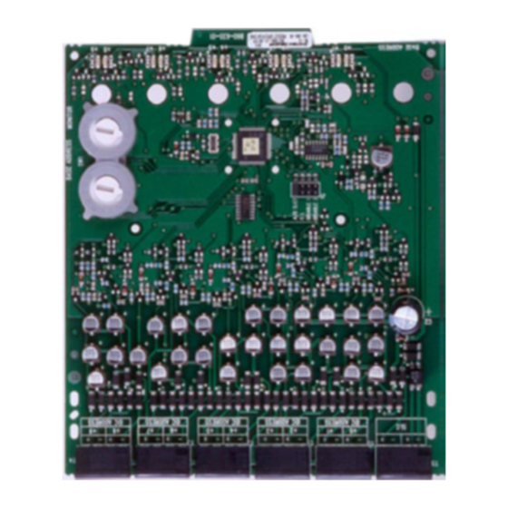
The FIK-IM-10 Ten Input Monitor Module is intended for use in an intelligent
alarm system. Each monitor module is intended to interface between a control
panel and normally open contact devices, such as pull stations. A common
SLC input is used for all modules, and the initiating device loops share a
common supervisory supply and ground. Otherwise, each monitor operates
independently from the others. Each module has its own unique address.
A pair of rotary code switches is used to set the address of the first mod-
ule from 01 to 150 (01 to 90 on panels that support up to 99 addresses).
The remaining modules are automatically assigned to the next nine higher
addresses. Provisions are included for disabling a maximum of two unused
modules to release the addresses to be used elsewhere. Each module also has
panel controlled green LED indicators. The panel can cause the LEDs to blink,
latch on, or latch off.
SHIPPED ON BOARD:
(1) Shunt in Class A/B position
(Shipped in Class B position, remove shunt for Class A)
INCLUDED:
(6) 1 x 4 Terminal
Blocks
(3) Shunts
(4) Machine Screws
(2) Nuts
15-32 VDC
3.75 mA @ 24V
55 mA (assumes all ten LEDs solid on)
32°F to 120°F (0°C to 49°C)
10 to 93% Non-condensing
6.8" H x 5.8" W x 1.25" D
FIK-BB-2 Cabinet and Chassis
12-18 AWG
1500 Ohms
10.2 VDC
240 µA (each circuit)
(2) 1¼" (32mm)
Stand offs
(10) 47k Ohm End
of Line Resistors
COMPATIBILITY REQUIREMENTS
To ensure proper operation, this module shall be connected to a compatible
Fike system control panel.
COMPONENTS
The following is a description of the FIK-IM-10 mounting framework:
• One or two FIK-IM-10 modules can be installed in an FIK-BB-2 cabinet.
The FIK-BB-2 cabinet has a built-in chassis that will accommodate one or two
FIK-IM-10 modules.
The front FIK-IM-10 module positions of each chassis are offset below the rear
FIGURE 1: FIK-BB-2 CABINET
FIK-IM-10 module positions so that all of the status indicators are visible. For
cabinet dimensions refer to the FIK-BB-2 instruction manual.
C0202-00
1
704 SW 10th Street
Blue Springs, MO 64015
Phone: 816.229.3405; Fax: 816.228.9277
www.fike.com
For system/product documentation including
installation, operation, and maintenance,
scan QR code or enter URL provided.
http://www.fike.com/06-912
C0234-05
I56-6893-000
1/15/2021
R
Advertisement
Table of Contents

Related Manuals for Fike FIK-IM-10


Summary of Contents for Fike FIK-IM-10
- Page 1 The following is a description of the FIK-IM-10 mounting framework: proper wrist strap before handling any circuits so that static charges are re- • One or two FIK-IM-10 modules can be installed in an FIK-BB-2 cabinet. moved from the body. The housing cabinet should be metallic and suitably grounded.
- Page 2 HOLES C0235-00 C0226-00 INSTALLATION STEPS Step 1: Insert the bottom edge of the FIK-IM-10 module down into a front slot Cabinet Mounting of the chassis. In a clean, dry area, mount the backbox using the four holes pro- Step 2: Carefully swing the upper edge of the board towards the back of the vided in the back surface of the cabinet.
- Page 3 – Consult the dealer or an experienced radio/TV technician for help. of the system that could result in information disclo- sure, spoofing, and integrity violation. Fike ® is a registered trademark of Fike Corporation. I56-6893-000 ©2021. 1/15/2021...
Need help?
Do you have a question about the FIK-IM-10 and is the answer not in the manual?
Questions and answers