Satel ACCO-KP2 Quick Installation Manual
Access control module acco
Hide thumbs
Also See for ACCO-KP2:
- User manual (21 pages) ,
- Manual (4 pages) ,
- Installer manual (21 pages)

Related Manuals for Satel ACCO-KP2


Summary of Contents for Satel ACCO-KP2
- Page 1 ACCO-KP2 Access control module ACCO QUICK INSTALLATION GUIDE Firmware version 1.00 acco-kp2_sii_en 03/22 SATEL sp. z o.o. • ul. Budowlanych 66 • 80-298 Gdańsk • POLAND tel. +48 58 320 94 00 www.satel.eu...
- Page 2 1wIP – under BSD license (https://savannah.nongnu.org/projects/1wip). SATEL aims to continually improve the quality of its products, which may result in changes in their technical specifications and software. Current information about the changes being introduced is available on our website.
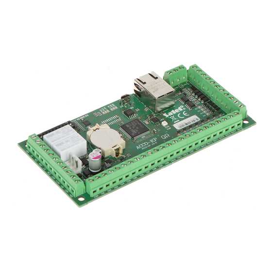
- Page 3 This manual contains basic information on how to install the ACCO-KP2 module. For further information, please refer to the full installer manual available at www.satel.eu. 1. Electronics board Fig. 1. Electronics board in ACCO-KP2 door controller module. APS connector for a SATEL power supply unit (e.g. APS-412).
- Page 4 ACCO-KP2 SATEL – reader B presence control [TMPB], – programmable input 1, – programmable input 2, – programmable input 3, IN10 – programmable input 4, IN11 – programmable input 5, IN12 – reader A sound control [BPA], OUT1 – reader A green LED control [LD1A], OUT2 –...
- Page 5 For the module to be able to execute the access control functions, it is necessary to connect to the module a user identification device, a device to activate the controlled door and a sensor to monitor the door status. 2.1 User identification devices (terminals) You can use the following SATEL devices for user identification: ACCO-KLCDR keypad, ...
- Page 6 reader: 30 m. 3.1.1 Connecting the ACCO-KLCDR keypad Fig. 4. Method of connecting the LCD keypad to the ACCO-KP2 module. The +G3 output is used as an example. You can use the +G1...+G4 outputs. The module supports LCD keypads with addresses 0 and 1. See full manual for description of the address setting procedure.
- Page 7 [CZ-EMM4] Bell signal Table 3. Method of connecting the SATEL reader to the module. The black wire is used when the CZ-EMM3 and CZ-EMM4 readers are working in the Wiegand format. It is recommended that the readers work in the EM-Marin format.
- Page 8 3.3 Connecting the power supply and starting the module Do not connect power supply until the installation work is completed. The ACCO-KP2 module requires power supply of 12 VDC (±15%). SATEL offers power supplies (e.g. APS-412), which can be connected to the APS connector on the electronics board.
Need help?
Do you have a question about the ACCO-KP2 and is the answer not in the manual?
Questions and answers