
Related Manuals for EM Acoustics R5


Summary of Contents for EM Acoustics R5
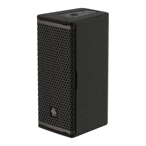
- Page 1 3-way compact precision point source loudspeaker Product User Manual v1 December 2023 l i b e r a t i n g a u d i o...
-
Page 2: Table Of Contents
Page 2 of 37 Contents DECLARATIONS OF CONFORMITY......................4 1.0 - Introduction ............................. 5 Unpacking ..............................5 2.0 – R5 & Accessories ........................... 6 R5 ..................................6 FC-R5h ................................6 FC-R5v ................................7 PM-61 Stand Adapter ..........................7 Cradle stand adapter ..........................7 2.1 –... - Page 3 7.0 – Servicing Information ........................26 7.1 – R5: Removing the grille ......................26 7.2 – R5: Removing the LF/MF drive units ..................27 7.3 – R5: Removing the HF drive unit ....................29 Appendix A – Technical Specifications ....................30 R5 compact 3-way precision passive point source loudspeaker ..........
-
Page 4: Declarations Of Conformity
DECLARATIONS OF CONFORMITY This declaration applies to: 10M605 – R5 compact 3-way precision passive point source loudspeaker This declaration also applies to all product variants, provided that they conform to the original technical specification and have not been subject to any non-factory modifications. -
Page 5: Introduction
Two waveguides are supplied with the R5 - 80° x 50° fitted as standard and 110° x 50° supplied loose. These three drive units are linked with a completely new type of passive crossover network, designed from the ground up to work in conjunction with the FIR (Finite Impulse Response) processing in the DQ Series advanced system amplifiers. -
Page 6: R5 & Accessories
NET/SHIPPING WEIGHT: 7/8.2kg (15.4/18lbs) FC-R5h The FC-R5h is a simple and effective means of mounting the R5 horizontally in Horizontal flying cradle both temporary and permanent applications. It is secured to the cabinet by means of two M8 hand knobs into the top and bottom of the loudspeaker to mount it in a landscape format. -
Page 7: Fc-R5V
The stand adapter is designed to support one single R5 loudspeaker. Weight (including fixings) 0.75kg / 1.7lbs Cradle stand adapter To allow the mounting of the R5 on a stand yet keeping the ability to tilt the loudspeaker, the R5 cradles can both be used with this optional accessory. Stand... -
Page 8: Determining The Installed Waveguide And Orientation
110° x 50° horn is fitted and is oriented so it is 50° in the vertical plane (and therefore 110° in the horizontal plane). By default, the R5 ships from the factory with the 80x50 waveguide fitted, and the dispersion pattern 80° horizontal x 50° vertical when the loudspeaker is in a portrait format. -
Page 9: Rotating The Hf Waveguide
The high frequency waveguide of the R5 can be easily rotated to provide appropriate dispersion in both portrait and landscape formats. By default, the R5 ships from the factory with the dispersion pattern 80° horizontal x 50° vertical when the loudspeaker is in a portrait format. -
Page 10: Changing The Hf Waveguide
Page 10 of 37 2.3 – Changing the HF waveguide The R5 is supplied with two waveguides for maximum flexibility – a narrow dispersion (80° x 50°) and a wide dispersion (110° x 50°). By default, the R5 ships from the factory with the dispersion pattern 80° horizontal x 50°... -
Page 11: Simulation
Tutorials for Ease Focus 3 are available from with the application itself. For training on the design and implementation of R5 loudspeakers including the specific use of Ease Focus 3, please contact your local distributor. -
Page 12: Safety Considerations
General Considerations in use Loudspeaker systems are potentially dangerous objects if used incorrectly. Please ensure that you read this section fully, and contact EM Acoustics or your local dealer should you be in any doubt over correct operation procedures. Personal Injury Never stand in the immediate vicinity of loudspeakers when in use at high level. -
Page 13: Ground Stacking
EM Acoustics is in no way liable for any loss, damage or injury caused by such practice. Do not modify or alter the R5 loudspeaker or accessories, nor use them in any way other than that described in this manual. Rigging components supplied with the R5 are in no way interchangeable and should not be used as such. -
Page 14: Secondary Safeties
In most cases, annual independent tests & inspections carried out by a suitably approved and qualified inspector will be required. EM Acoustics recommends detailed logbooks be kept of all inspections and load tests to ensure an accurate record is kept of the testing for each EM Acoustics rigging accessory. -
Page 15: Rigging & Mounting Options
Page 15 of 37 5.0 – Rigging & Mounting Options 5.1 – R5 Cabinet Overview Top M8 mounting point Quick-release flying attachment plate Rear M8 safety point Bottom M8 stand adapter/safety point M6 Omnimount/Powerdrive attachment point R5 User Manual v1 December 2023... -
Page 16: Using The Fc-R5V
Page 16 of 37 5.2 – Using the FC-R5v The FC-R8v is intended to mount the R5 vertically – either using a hook clamp or similar from above, or a pole mount adapter to mount on a stand yet allowing enclosure tilt (see chapter 5.6). -
Page 17: Using The Fc-R5H
Page 17 of 37 5.3 – Using the FC-R5h The FC-R5h is intended to mount the R5 horizontally. To fit, lie the R5 on its side and line the flying cradle up with the mounting holes in the desired location (see 5.3.1 below). -
Page 18: Using The Pm-61 Stand Adapter
35mm loudspeaker stand or distance pole. To fit, simply lie the R5 on its back or stand it on its top, line the PM-61 up with the M8 mounting hole on the base of the enclosure. -
Page 19: Using The Cradle Stand Adapter
Safeties should always be arranged so that the loudspeaker cannot drop in the event of a primary attachment point failing so select the most appropriate safety point considering the rigging situation. M8 safety points R5 User Manual v1 December 2023... -
Page 20: Using Powerdrive Or Omnimount Fittings
Using a 4mm Allen key, remove the four M6 countersunk socket head bolts on the rear of the R5. The mounting bracket can then be attached using the bolts supplied with the bracket – they must be M6 thread, minimum 25mm in length. Ensure flat washers are in contact with the bracket, and the spring washer is in between the bolt head and the flat washer. -
Page 21: Powering The System
6.1 - Amplifier and Processing Requirements 6.1.1 - Connections The R5 requires only a single amplifier channel. Inputs to the R5 enclosure are on Neutrik SpeakON NL4 as illustrated below. Two-core cable should be used for connecting R5 loudspeakers, and the connections are... -
Page 22: Amplifier Requirements
A loudspeaker is far more likely to be damaged by an under-powered amplifier working too hard, than an over-powered amplifier working well within its limits. All of the DQ and Di Series advanced system amplifiers can be used to power the R5 with some considerations shown below. -
Page 23: Presets And Settings
6.2 - Presets and Settings 6.2.1 – Standard R5 presets When used with a DQ or Di Series amplifier R5 loudspeakers require only a single amplifier channel, and as such the preset recalled will only require one output from your amplifier. -
Page 24: Use With The Dq & Di Series Advanced System Amplifiers
6.3 - Use with the DQ & Di Series Advanced System Amplifiers The R5 is designed to be used with DQ or Di Series advanced system amplifiers, as not only are they state-of-the-art amplifiers, but the onboard DSP provides appropriate processing to allow the R5 to perform as intended. -
Page 25: System Connectivity
Because pins 2+/2- are linked through inside all EM Acoustics loudspeakers, using a 4-core cable to one loudspeaker (carrying two different signals) allows a crossover cable to be used to link out of the first loudspeaker into another, thereby feeding it from a separate signal. -
Page 26: Servicing Information
To replace the grille, position the grille on the front of the R5 and ensure the threaded fittings on the grille are lined up with the mounting holes – gentle pressure may be required. Replace all of the M6x30 countersunk socket screws and ensure they are all are started in their threads before beginning to tighten. -
Page 27: R5: Removing The Lf/Mf Drive Units
Page 27 of 37 7.2 – R5: Removing the LF/MF drive units TOOLS REQUIRED: 3mm & 4mm Allen keys Complete step 7.1 above to remove the grille. Using a 4mm Allen key, remove the two M6x16 button head socket screws that secure the HF waveguide. - Page 28 With the waveguide in the correct orientation, replace the M6x16 button head socket screws and retighten. 10. Replace the grille as described above. R5 User Manual v1 December 2023...
-
Page 29: R5: Removing The Hf Drive Unit
Page 29 of 37 7.3 – R5: Removing the HF drive unit TOOLS REQUIRED: 3mm, 4mm & 5mm Allen keys, TX30 Torx driver Complete step 7.1 above to remove the grille, and step 7.2 above to remove the HF waveguide, occlusion bowl and the upper 5”... -
Page 30: Appendix A - Technical Specifications
Page 30 of 37 Appendix A – Technical Specifications R5 compact 3-way precision passive point source loudspeaker Dimensions (HxWxD): 400 x 172 x 210mm (15.8” x 6.8” x 8.3”) Net/Shipping Weight: 7/8.2kg (15.4/18lbs) Frequency Response (+/- 3dB) 80Hz – 20kHz Dispersion 80°... -
Page 31: Appendix B - Technical Drawings
Page 31 of 37 Appendix B – Technical Drawings R5 User Manual v1 December 2023... - Page 32 Page 32 of 37 R5 User Manual v1 December 2023...
- Page 33 Page 33 of 37 R5 User Manual v1 December 2023...
- Page 34 Page 34 of 37 R5 User Manual v1 December 2023...
- Page 35 Page 35 of 37 R5 User Manual v1 December 2023...
-
Page 36: Appendix C - Spare Parts List
DU-503-16 replacement 5” neodymium LF/MF drive unit 01B017 CDU-1005-16 replacement 1” neodymium HF compression drive unit 04A089 RFG-R5 replacement grille/fabric for R5 07A504A PX-R5-MHF replacement mid/high passive crossover assembly for R5 07A504B PX-R5-LF replacement low/mid passive crossover assembly for R5 R5 User Manual v1 December 2023... -
Page 37: Appendix D - Warranty Information
Serial numbers must be quoted in all correspondence relating to the claim. EM Acoustics or its representatives are in no way liable for any loss or damage in transit, and hence it is recommended that the sender insure the shipment. EM Acoustics will pay for return freight should the repair be covered under warranty.
Need help?
Do you have a question about the R5 and is the answer not in the manual?
Questions and answers