
Related Manuals for EM Acoustics EMS-41


Summary of Contents for EM Acoustics EMS-41
- Page 1 EMS-41 ultra-compact two-way passive fill loudspeaker Product User Manual v1 November 2019 L O U D S P E A K E R S D E F I N E D...
-
Page 2: Table Of Contents
Page 2 of 25 Contents DECLARATION OF CONFORMITY .........................4 1.0 - Introduction ..............................5 Unpacking ...............................5 2.0 – EMS-41 & Accessories ..........................6 EMS-41 ................................6 BM-41 ................................6 YK-41h ................................6 WP-41 ................................7 3.0 – Simulation ..............................8 Ease Focus 3 ..............................8 4.0 - Safety Considerations ..........................9 General Considerations in use.........................9... - Page 3 6.4.2 – Crossover Cable Use ......................19 7.0 – Servicing Information ........................20 7.1 – EMS-41: Removing the grille ..................... 20 7.2 – EMS-41: Removing the drive unit ................... 21 Appendix A – Technical Specifications ....................22 EMS-41 ultra-compact passive loudspeaker................... 22 Appendix B –...
-
Page 4: Declaration Of Conformity
The packaging supplied with this product is recyclable. Please retain all packaging, however if disposing of this packaging please ensure that you comply with local recycling regulations. These products also all comply to the RoHS Directive 2002/95/EC. EMS-41 User Manual v1 November 2019... -
Page 5: Introduction
EM Acoustics representative. The EMS-41 is an extremely compact 2-way loudspeaker, intended for a wide variety of discreet applications – from theatrical fills and delays right through to theme park attractions. -
Page 6: Ems-41 & Accessories
EMS-41 loudspeaker. An M8 thread engages in the loudspeaker itself, and an M10 female thread is presented to allow attachment to other mounting hardware. The BM-41 secures into the EMS-41 by a single M8 mounting point – either the top, bottom or more commonly the rear point. Weight 0.15kg / 0.33lbs... - Page 7 Wall mounting plate The WP-41 is intended to be used in conjunction with the BM-41 ball-joint adapter for fixing EMS-41 loudspeakers to walls or ceilings in a fixed installation environment. An M10 stud attaches to the female thread on the BM-41, providing a safe and secure means of installing EMS-41 loudspeakers discreetly.
-
Page 8: Simulation
Tutorials for Ease Focus 3 are available from with the application itself. For training on the design and implementation of EMS-41 loudspeakers including the specific use of Ease Focus 3, please contact your local distributor. -
Page 9: Safety Considerations
General Considerations in use Loudspeaker systems are potentially dangerous objects if used incorrectly. Please ensure that you read this section fully, and contact EM Acoustics or your local dealer should you be in any doubt over correct operation procedures. Personal Injury Never stand in the immediate vicinity of loudspeakers when in use at high level. -
Page 10: Ground Stacking
EM Acoustics is in no way liable for any loss, damage or injury caused by such practice. Do not modify or alter the EMS-41 loudspeaker or accessories, nor use them in any way other than that described in this manual. Rigging components supplied with the EMS-41 are in no way interchangeable and should not be used as such. -
Page 11: Secondary Safeties
In most cases, annual independent tests & inspections carried out by a suitably approved and qualified inspector will be required. EM Acoustics recommends detailed logbooks be kept of all inspections and load tests to ensure an accurate record is kept of the testing for each EM Acoustics rigging accessory. -
Page 12: Rigging & Mounting Options
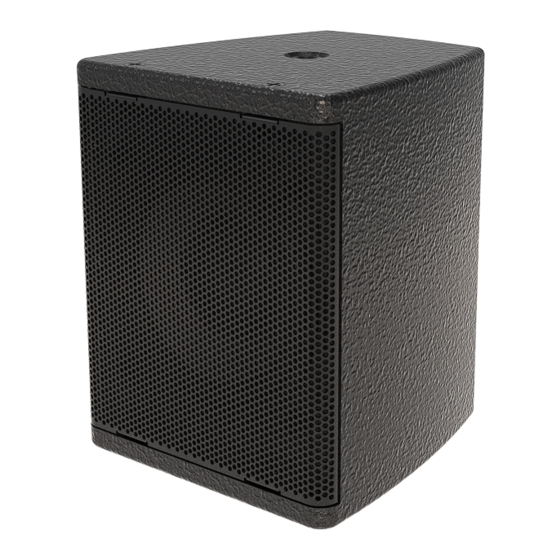
Page 12 of 25 5.0 – Rigging & Mounting Options 5.1 – EMS-41 Cabinet Overview Top/Bottom M8 mounting point Rear M8 mounting point EMS-41 User Manual v1 November 2019... -
Page 13: Using The Yk-41H
EMS-41. 5.3 – Using the BM-41 The BM-41 can be attached to any of the M8 threaded fittings on the EMS-41 but was primarily intended to attach to the back panel. Simply screw the BM-41 into the back of the EMS-41. -
Page 14: Using The Bm-41 With The Wp-41 Wall Plate
Always ensure that a secondary safety is used when suspending any loudspeaker. 5.5 – Using thread adapters Various thread adapters are available to convert the M8 thread on an EMS-41 to a 3/8” UNC thread to fit standard microphone stands. The threaded point has a depth of 15mm, and is a standard M8 thread. -
Page 15: Powering The System
The four-pole Phoenix connector provides access to the positive and negative input terminals of the EMS-41, in two parallel pairs of pins. In this way, either a single 4-way connector or a pair of 2-way connectors can be used, keeping input and enclosure link output on separate connections. -
Page 16: Amplifier Requirements
All of the DQ Series advanced system amplifiers can be used to power the EMS-41. The following table shows the maximum number of EMS-41 that can be connected per... -
Page 17: Presets And Settings
The EMS-41 is designed with a significant amount of system headroom, so applying EQ is perfectly acceptable within sensible limits. -
Page 18: Use With The Dq Series Advanced System Amplifiers
Page 18 of 25 6.3 - Use with the DQ Series Advanced System Amplifiers The EMS-41 will perform best when using DQ Series advanced system amplifiers, as not only are they state-of-the-art amplifiers, but the onboard DSP provides appropriate high/low pass filter settings and limiters to get the best from your subwoofers. -
Page 19: System Connectivity
Signal for first loudspeaker on pins 1+/1-, signal for second EMS-41 loudspeaker on pins 2+/2-. Crossover cable specifications Connector A Pin Connector B Pin A crossover cable can only be used on the speakON connections on the EMS-41, not on the Phoenix connector. EMS-41 User Manual v1 November 2019... -
Page 20: Servicing Information
PZ2 screws To replace the grille, position the grille on the front of the EMS-41 and ensure the threaded fittings on the grille are lined up with the mounting holes – gentle pressure may be required. Replace each of the four M4x14 countersunk screws and ensure all machine screws are started in their threads before beginning to tighten. -
Page 21: Ems-41: Removing The Drive Unit
Page 21 of 25 7.2 – EMS-41: Removing the drive unit TOOLS REQUIRED: 3mm Allen key Complete step 7.1 above to remove the grille. Using a 3mm Allen key, remove the four M4x16 button head socket screws that secure the drive unit. -
Page 22: Appendix A - Technical Specifications
Page 22 of 25 Appendix A – Technical Specifications EMS-41 ultra-compact passive loudspeaker Dimensions (HxWxD): 150 x 120 x 130mm (5.9” x 4.7” x 5.1”) Net/Shipping Weight: 1.6kg/2.4kg (3.5/5.3lbs) Frequency Response (+/- 3dB) 100Hz – 20kHz Dispersion 80° conical Drive Units: Coaxial neodymium 4”... -
Page 23: Appendix B - Technical Drawings
Page 23 of 25 Appendix B – Technical Drawings EMS-41 User Manual v1 November 2019... -
Page 24: Appendix C - Spare Parts List
Page 24 of 25 Appendix C – Spare Parts List Order Code Description 01A507 CAD-401 replacement 4”/0.85” coaxial drive unit 04A049 RFG-41 replacement grille for EMS-41 EMS-41 User Manual v1 November 2019... -
Page 25: Appendix D - Warranty Information
Serial numbers must be quoted in all correspondence relating to the claim. EM Acoustics or its representatives are in no way liable for any loss or damage in transit, and hence it is recommended that the sender insure the shipment. EM Acoustics will pay for return freight should the repair be covered under warranty.
Need help?
Do you have a question about the EMS-41 and is the answer not in the manual?
Questions and answers