Table of Contents
Advertisement
nordictrack.com
Model No. NTL19819A.5
Serial No.
Write the serial number in the space
above for reference.
Serial
Number
Decal
REGISTER YOUR
PRODUCT
To register your product and
activate your warranty today,
go to my.nordictrack.com.
MEMBER CARE
For service at any time, go to
my.iFIT.com or scan the QR code.
Please do not contact the store.
CAUTION
Read all precautions and
instructions in this manual before
using this equipment. Keep this
manual for future reference.
USER'S MANUAL
Advertisement
Table of Contents

Related Manuals for iFIT NordicTrack T 7.5 S


Summary of Contents for iFIT NordicTrack T 7.5 S
- Page 1 To register your product and activate your warranty today, go to my.nordictrack.com. MEMBER CARE For service at any time, go to my.iFIT.com or scan the QR code. Please do not contact the store. CAUTION Read all precautions and instructions in this manual before using this equipment.
-
Page 2: Table Of Contents
Apply the decal in the location shown. Note: The decals may not be shown at actual size. NORDICTRACK and IFIT are registered trademarks of iFIT Inc. The Bluetooth word mark and logos are regis- ® tered trademarks of Bluetooth SIG, Inc. and are used under license. Google Maps is a trademark of Google LLC. -
Page 3: Important Precautions
To reduce the risk of burns, fire, electric shock, or injury to persons, read all important precautions and instructions in this manual and all warnings on your treadmill before using your treadmill. iFIT assumes no responsibility for personal injury or property damage sus- tained by or through the use of this product. - Page 4 19. Read, understand, and test the emergency 26. When folding or moving the treadmill, make stop procedure before using the treadmill sure that the storage latch is holding the (see HOW TO TURN ON THE CONSOLE on frame securely in the storage position. Do page 20).
-
Page 6: Before You Begin
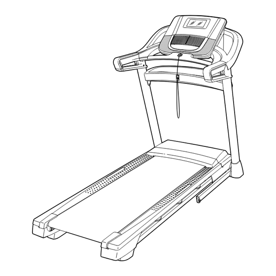
BEFORE YOU BEGIN Thank you for selecting the new NORDICTRACK manual. To help us assist you, note the product model ® T 7.5 S treadmill. The T 7.5 S treadmill provides an number and serial number before contacting us. The impressive selection of features designed to make your model number and the location of the serial number workouts at home more effective and enjoyable. -
Page 7: Part Identification Chart
PART IDENTIFICATION CHART Use the drawings below to identify small parts used for assembly. The number in parentheses below each draw- ing is the key number of the part, from the PART LIST near the end of this manual. The number following the key number is the quantity used for assembly. -
Page 8: Assembly
ASSEMBLY • Assembly requires two persons. • To identify small parts, see page 7. • Place all parts in a cleared area and remove the • Assembly requires the following tools: packing materials. Do not dispose of the packing the included hex keys materials until you finish all assembly steps. - Page 9 2. Make sure that the power cord is unplugged. Locate the Upright Wire (81) on the right side of the Base (94). Remove the wire tie (not shown) securing the Upright Wire to the Base. Next, identify the Right Upright (90), and have a second person hold it near the Base (94).
- Page 10 4. Hold the Right Upright (90) against the Base (94). Do not to pinch the Upright Wire (81). Attach the Right Upright (90) with four 3/8" x 3/4" Screws (7) and four 3/8" Star Washers (13); do not fully tighten the Screws yet. Attach the Left Upright (not shown) in the same way.
- Page 11 6. Identify the left handrail assembly (E). Attach the left handrail assembly to the Left Upright (89) with two 5/16" x 2 1/2" Screws (28) and two 5/16" Star Washers (11); do not fully tighten the Screws yet. Then, remove and discard the indicated screw (F).
- Page 12 8. Tighten four #8 x 3/4" Screws (2) into the left and right handrail assemblies (E, G) and into the Left and Right Uprights (89, 90). 9. Set the Console Base (64) facedown on a soft surface to avoid scratching the Console Base. If there are ties (H) securing the Crossbar (93) to the Console Base, remove the ties.
- Page 13 10. Identify the Right Tray (27). Hold the Right Tray (27) near the Console Base (64), and slide the indicated tab (S) onto the indi- cated pin (U) in the Console Base. Then, attach the Right Tray with three #8 x 1/2" Screws (10); do not overtighten the Screws.
- Page 14 12. See the inset drawing. Grip the connector on the Upright Wire (81). Then, press the small latch (T) on the wire pull (B), and remove and discard the wire pull and the wire tie. Next, have a second person hold the console assembly (J) near the Handrails (86).
- Page 15 14. Attach the Crossbar (93) to the console assem- bly (J) with four #8 x 5/8" Screws (1); start all four Screws, and then tighten them. Then, firmly tighten the four 5/16" x 3/4" Screws (4). 15. Orient the Upright Crossbar (98) as shown. Carefully slide the Upright Crossbar (98) between the Left and Right Uprights (89, 90).
- Page 16 17. Note: If the treadmill is assembled on a smooth surface, it may roll forward in this step. Remove the two 5/16" x 3/4" Screws (4) from the Latch Crossbar (41). Note: The Latch Crossbar is not preattached to the treadmill. Raise the Frame (56) to the upright position.
- Page 17 19. Remove the 5/16" Nut (34) and the 5/16" x 2 1/4" Bolt (3) from the bracket on the Latch Crossbar (41). Align the upper end of the Storage Latch (53) with the bracket on the Latch Crossbar (41), and insert the 5/16" x 2 1/4" Bolt (3) through the bracket and the Storage Latch.
-
Page 18: How To Plug In The Power Cord
HOW TO PLUG IN THE POWER CORD USE A SURGE SUPPRESSOR overloading the circuit, do not plug other electrical devices, except for low-power devices such as cell Your treadmill, like other electronic equipment, can be phone chargers, into the surge suppressor or into damaged by sudden voltage changes in your home’s an outlet on the same circuit. -
Page 19: How To Use The Treadmill
When you use the manual mode of the console, you... - Page 20 1. Connect to your wireless network. measurement is selected, see HOW TO CHANGE CONSOLE SETTINGS on page 27. To use iFIT workouts and to use several other features of the console, the console must be con- nected to a wireless network. Follow the prompts...
- Page 21 To use a heart rate monitor, see HOW TO USE featured workout, see page 23. To create a draw- AN OPTIONAL HEART RATE MONITOR on your-own-map workout, see page 24. To use an iFIT page 29. workout, see page 25.
- Page 22 Speed slider on the screen—When you touch Drag upward on the screen to enter the fullscreen and drag the speed slider, the walking belt will display mode. Drag downward on the screen to gradually change speed until it reaches the view the workout information displays.
- Page 23 5 on page 22). ing the favorites button (heart symbol). You must be logged into your iFIT account to save a featured To return to the programmed speed and/or incline settings of the workout, touch Follow Workout.
- Page 24 To use a draw-your-own-map workout, you must be the workout. The actual number of calories that logged into your iFIT account (see step 3 on page 25) you burn will depend on various factors, such and the console must be connected to a wireless as your weight.
- Page 25 (see step 5 on page 23). button (three horizontal lines symbol) on the screen and then touch Log in to log in to your iFIT account. Follow the prompts on the screen to enter your 7. When you are finished using the treadmill, turn username and password.
- Page 26 See HOW TO TURN OFF THE CONSOLE on screen. page 20. 6. Create a list of favorite iFIT workouts if desired. For more information about iFIT, go to iFIT.com. To mark an iFIT workout as a favorite, simply view the overview or workout summary of the desired iFIT workout and touch the favorites button (heart symbol).
- Page 27 HOW TO CHANGE CONSOLE SETTINGS 3. Customize workout settings. To customize workout settings and enable work- IMPORTANT: Firmware updates (see step 6) out features, touch In Workout and then touch the are always designed to improve your exercise experience. As a result, new settings and features desired settings.
- Page 28 HOW TO CONNECT TO A WIRELESS NETWORK screen. To use iFIT workouts and to use several other features of the console, the console must be connected to a If you are having problems connecting to an wireless network.
-
Page 29: Fcc Information
HOW TO USE THE FAN HOW TO USE AN OPTIONAL HEART RATE MONITOR The fan has several speed settings, including an auto Whether your mode. While the auto mode is goal is to selected, the speed of the fan burn fat or to will automatically increase or strengthen your decrease as the speed of the walking belt increases or... -
Page 30: How To Fold And Move The Treadmill
HOW TO FOLD AND MOVE THE TREADMILL HOW TO FOLD THE TREADMILL HOW TO MOVE THE TREADMILL Before moving the treadmill, fold it as described at the To avoid damaging the treadmill, adjust the incline left. CAUTION: Make sure that the storage latch is to 0% before you fold the treadmill. -
Page 31: Maintenance And Troubleshooting
If further assistance is needed, d. If the treadmill still will not run, please see the go to my.iFIT.com, scan Member Care information at the left. the QR code at the right, or call 1-833-680-IFIT (1-833-680-4348). - Page 32 SYMPTOM: The walking belt slows when walked on SYMPTOM: The walking belt is off-center a. Use only a surge suppressor that meets all of the a. First, remove the key and UNPLUG THE POWER specifications described on page 18. CORD. If the walking belt has shifted to the left, use the hex key to turn the left idler roller screw b.
-
Page 33: Exercise Guidelines
EXERCISE GUIDELINES Aerobic Exercise—If your goal is to strengthen your WARNING: cardiovascular system, you must perform aerobic Consult your health exercise, which is activity that requires large amounts care provider before beginning any exercise of oxygen for prolonged periods of time. For aerobic program. -
Page 34: Part List
PART LIST Model No. NTL19819A.5 R0723A Key No. Qty. Description Key No. Qty. Description #8 x 5/8" Screw Drive Roller/Pulley #8 x 3/4" Screw 1/4" x 1 1/4" Screw 5/16" x 2 1/4" Bolt 9/32" Plastic Bushing 5/16" x 3/4" Screw 3/8"... - Page 35 Key No. Qty. Description Key No. Qty. Description Base Pad 5/16" Bushing U-bracket Upright Crossbar Left Inner Base Cover – User’s Manual Right Inner Base Cover Note: Specifications are subject to change without notice. For information about ordering replacement parts, see the back cover of this manual.
-
Page 36: Exploded Drawing
EXPLODED DRAWING A Model No. NTL19819A.5 R0723A... - Page 37 EXPLODED DRAWING B Model No. NTL19819A.5 R0723A...
- Page 38 EXPLODED DRAWING C Model No. NTL19819A.5 R0723A...
- Page 39 EXPLODED DRAWING D Model No. NTL19819A.5 R0723A...
-
Page 40: Ordering Replacement Parts
This warranty extends only to the original purchaser (customer) and is not transferrable. iFIT’s obligation under this warranty is limited to repairing or replacing, at iFIT’s discretion, the product through one of its authorized service providers. All repairs for which warranty claims are made must be preauthorized by iFIT.
Need help?
Do you have a question about the NordicTrack T 7.5 S and is the answer not in the manual?
Questions and answers
How do you free up internal memory on your on your treadmill?
My Nordic Trak 1750 Commercial treadmill was not used for several months and, now, will not turn on. It keeps showing an iFit error message.