
Related Manuals for Advantech POC-S198-25F-ACE


Summary of Contents for Advantech POC-S198-25F-ACE
- Page 1 User Manual POC-S198 19" Slim Point-of-Care Termminal with True Flat Panel and IP54 Enclosure...
- Page 2 Repair of the device may only be carried out by trained service personnel. Advantech recommends that a service contract be obtained with Advantech Service and that all repairs also be carried out by them. Otherwise the correct functioning of the device may be compromised.
- Page 3 If one of the following situations arises, have the equipment checked by service personnel: The power cord or plug is damaged. Liquid has penetrated into the equipment. The equipment has been exposed to moisture. The equipment does not work well, or you cannot get it to work according to the user manual.
- Page 4 Caution! When servicing the device, always use replacement parts that are quali- fied to Advantech standards. Advantech Digital Healthcare cannot war- rant or endorse the safe performance of third-party replacement parts for use with our medical device.
- Page 5 Furthermore all configurations shall comply with the system standard IEC 60601-1-1. Anyone who connects additional equipment to the signal input part or signal output part is configuring a medical system, and is therefore, responsi- ble that the system complies with the requirements of the system standard IEC 60601-1-1.
- Page 6 Disposing of Old Products Within the European Union EU-wide legislation, as implemented in each member state, requires that waste electrical and electronic products carrying the mark shown at left must be disposed of separately from normal household waste. This includes monitors and electrical accesso- ries, such as signal cables or power cords.
- Page 7 Otherwise the correct functioning of the device may be compromised. Additional Information and Assistance Contact your distributor, sales representative, or Advantech's customer service cen- ter for technical support if you need additional assistance. Please have the following information ready before you call: ...
- Page 8 POC-W211 User Manual...
-
Page 9: Table Of Contents
Contents Chapter General Information ......1 Introduction ....................2 Specifications .................... 2 Dimensions ....................4 Figure 1.1 Dimensions of the POC-S198 ........4 Figure 1.2 VESA Mounting of the POC-S198 ......4 Figure 1.3 POC-S198 Front Panel..........5 Figure 1.4 POC-S198 Back I/O ..........5 1.3.1 Optional Modules ................ - Page 10 Thermal....................26 Disconnect the Power ................26 Chapter PCM-8713 Connector Map and Table Motherboard Top Side ................30 Motherboard Bottom Side ............... 30 Table 6.1: MB Connector Table ..........31 I/O Board....................31 Table 6.2: I/O Connector Table ..........32 Chapter PCM-8713 Jumper Settings....
-
Page 11: General Information
Chapter General Information... -
Page 12: Introduction
It should not be used as a life-support system. The latest version of this user manual is available for download from http://support.advantech.com.tw/support/ Specifications Chipset Intel QM67 Intel Core i7-3555LE Processor (4M Cache, 2.5... - Page 13 Type A Type B 1 x RS-232 (isolated) 1 x RS-232 Serial Ports 2 x RS-232 (isolated) 1 x RS-232/422/485 1 x RS-232/422/485 (isolated) serial port (isolated) serial port USB 2.0 Ports DVI Ports I/O Ports Speakers (1W) 2 x 2W 2 x 2W 2 x Gigabit Ethernet 1 x Gigabit Ethernet...
-
Page 14: Dimensions
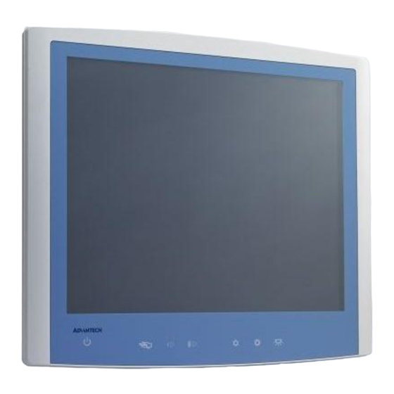
Dimensions Dimensions: 550 x 370 x 65 mm (Unit: mm) Figure 1.1 Dimensions of the POC-S198 VESA Mounting: 75 x 75 mm; 100 x 100 mm Figure 1.2 VESA Mounting of the POC-S198 Warning! Use suitable mounting apparatus to avoid risk of injury. POC-S198 User Manual... - Page 15 Figure 1.3 POC-S198 Front Panel Power Touchscreen Status Control Volume Down/Up Touchscreen Status Control Read Light Control Figure 1.4 POC-S198 Back I/O DC-IN USB 2.0 x4 DVI-Ix1 GigaLAN x2 RS-232 x1 232/422/485 POC-S198 User Manual...
- Page 16 DC-IN Figure 1.5 POC-S198 Back I/O USB 2.0 x3 RS-232 x1 GigaLAN x2 RS-232 x2 RS-232/422/485 x1 1.3.1 How to setup IP54 wiring POC-S198 User Manual...
-
Page 17: 1.3.2 Optional Modules
1.3.2 Optional Modules Battery Module(4200mAh Li-ion battery) RFID module Bluetooth module WLAN module(802.11a/b/g/n) POC-S198 User Manual... -
Page 18: Point-Of-Care Terminal Cleaning And Disinfecting
Point-of-Care Terminal Cleaning and Disinfecting During normal use of the POC (Point-of-Care Terminal) the device may become dirty and should be regularly cleaned. Steps: Prepare cleaning agent per manufacturer's instructions or hospital protocol. Wipe the POC with a clean cloth that has been moistened in the cleaning solu- tion. -
Page 19: System Setup
Chapter System Setup... -
Page 20: A Quick Tour Of The Poc-S198
A Quick Tour of the POC-S198 Before you start to set up the POC-S198, take a moment to become familiar with the locations and purposes of the controls, drives, connections and ports, which are illus- trated in the figures below. When you place the POC-S198 upright on the desktop, its front panel appears as shown in Figure 2.1. -
Page 21: Bottom View
2.1.2 Bottom View Bottom View: (1)PowerFigure 2.2 POC-S198 Front Panel (2)Touchscreen Status Control (3)Volume Down/Up (4)Touchscreen Status Control (5)Read Light Control 2.1.3 Rear View When you turn the Point-of-Care Terminal around and look at its rear cover, the sunken I/O section is at the bottom of the panel PC, as shown in Figure 2.3 and Fig- ure 2.4 (zoom view). - Page 22 Figure 2.3 Rear view of the Point-of-Care Terminal Figure 2.4 Rear view of Multi I/O ports Rear View: (1) DC-IN (2) USB 2.0 X4 (3) DVI-I X1 (4) GigaLAN X2 (5) RS-232 X1 (6) RS-232/422/485 X1 Rear View: (1) DC-IN (2) USB 2.0 X3 (3) RS-232 X1 (4) GigaLAN X2...
-
Page 23: Installation Procedures
Installation Procedures 2.2.1 Connecting the Power Cord The POC-S198 can only be powered by a DC power adapter (SINPRO Model no.HPU101-107). Be sure to always handle the power cords by holding the plug ends only. Follow these procedures in order: Connect the female end of the power adapter to the DC jack of the panel PC. -
Page 24: Connecting The Ground Pin
Switching on the power: Push down the power button on the front panel for POC-S198. (The color indicator turns green) Figure 2.7 Connecting the Power Cord 2.2.2 Connecting the Ground Pin With system ready, find the equipotential terminal on the rear side of the POC. -
Page 25: Running The Bios Setup Program
Prepare the grounding cable and the other terminal link to hospital ground/earth system. Figure 2.9 Grounding cable with connector Grounding cable plug with Equipotential Terminal Running the BIOS Setup Program Your POC-S198 was probably set up and configured by your dealer prior to delivery. You may still find it necessary to use the BIOS (Basic Input-Output System) setup program to change system configuration information, such as the current date and time or your type of hard drive. -
Page 26: Installing The Drivers
your hard drive, and installation of the operating system. Installing the Drivers After installing your system software, you will be able to set up the Chipset, Graphics, Ethernet, Audio, Touchscreen and AMT functions from your own external CD-ROM drive. All the drivers except the CD-ROM drive driver are stored in a CD-ROM disc entitled "Drivers and Utilities."... - Page 28 For your reference, the directories of drivers on the "Drivers and Utilities" CD-ROM are located as follows: XP Driver List: These drivers are located in the driver CD\Driver\XP folder Please follow the sequence below to install driver. Install Sequence Folder Name Note Chipset Please install chipset driver first.
- Page 29 Note! The drivers and utilities used for the POC-S198 panel PCs are subject to change without notice. If in doubt, check Advantech's website or con- tact our application engineers for the latest information regarding drivers and utilities. Troubleshooting When system behaves abnormally, such as:...
- Page 30 Recommended Separation Distances Between Portable and Mobile RF Communications Equipment and the POC-S198 POC-S198 is intended for use in an electromagnetic environment in which radiated RF disturbances are controlled. The customer or the user of the model POC-S198 can help prevent electromagnetic interference by maintaining a minimum distance between portable and mobile RF communications equipment (transmitters) and the model POC-S198 as recommended below, according to the maximum output power of the communications...
- Page 31 Guidance and Manufacturer’s Declaration – Electromagnetic Immunity POC-S198 is intended for use in the electromagnetic environment specified below. The customer or the user of the model POC-S198 should assure that it is used in such an envi- ronment. IEC 60601 Test Compliance Electromagnetic Environ- Immunity Test...
- Page 32 Guidance and Manufacturer’s Declaration – Electromagnetic Immunity The model POC-S198 is intended for use in the electromagnetic environment specified below. The customer or the user of the model POC-S198 should assure that it is used in such an environment. Immunity IEC 60601 Test Compliance Electromagnetic Environmental...
- Page 33 Field strengths from fixed transmitters, such as base stations for radio (cellular/cordless) telephones and land mobile radios, amateur radio, AM and FM radio broadcast and TV broadcast cannot be predicted theoretically with accuracy. To assess the electromagnetic environment due to fixed RF transmitters, an electromagnetic site survey should be consid- ered.
-
Page 34: Driver Installation
Chapter Driver Installation POC-S198 User Manual... -
Page 36: Introduction
Introduction The POC-S198 supports "one key" driver installation. User can just click one button to install all drivers. Warning! Please use clean OS to install this auto installation, otherwise, it might cause un-expect error. Automatic Driver Installation Double Click "InstallAll.exe" in D:\Driver\ folder. The Install dialog will appear. Please follow the instruction to install the driver POC-S198 User Manual... -
Page 37: Utilities And Hot Fixes
Chapter Utilities and Hot Fixes... -
Page 38: Introduction
Introduction The POC-S198 system needs specific utilities or hot fixes to support special func- tions. Wakeup by External USB Device at S3 Resume (Wakeup) POC-S198 supports three different sleep (suspend) modes; they are: S1: Power On Suspend: system will stop the clock, turn off LCD backlight, but keep all power on. -
Page 39: Operation And Safety
Chapter Operation and Safety Information... -
Page 40: General Safety Guide
General Safety Guide For your own safety and that of your equipment, always take the following precau- tions. Disconnect the power plug (by pulling the plug, not the cord), from your computer if any of the following conditions exists: The power cord or plug becomes frayed or otherwise damaged ... - Page 41 Warning! Never push objects of any kind into this product through the openings in the case. Doing so may be dangerous and result in fire or a dangerous electric shock. Never place anything on system case before turning off the computer. Never turn on your computer unless all of its internal and external parts are in place.
-
Page 42: Pcm-8713 Connector Map And Table
Chapter PCM-8713 Connector Map and Table POC S198 User Manual... -
Page 44: Motherboard Top Side
Motherboard Top Side Motherboard Bottom Side POC- S198 User Manual... -
Page 45: I/O Board
Table 6.1: MB Connector Table Description LVDS Connector EC SMBUS Connector FAN (Reserved) SATA 0 Connector LED Driver/Inverter Connector SATA 0 Power Connector DDR3 SODIMM A Socket DDR3 SODIMM B Socket SATA 1 Connector SATA 1 Power Connector 5-Wire Resistive Touch Connector USB (Reserved) BIOS Flash Port (Reserved) Mini PCIe Socket... - Page 46 Table 6.2: I/O Connector Table Description USB Connector (Reserved) USB Connector Internal Backup Battery Connector DCIN USB I/O x4 HDMI LAN (iAMT) x2 COM x2 4COM Table 6.2: I/O Connector Table Description USB Connector (Reserved) USB Connector Internal Backup Battery Connector DC IN USB I/O x3 LAN (iAMT) x2...
-
Page 47: Pcm-8713 Jumper Settings
Chapter PCM-8713 Jumper Settings... -
Page 48: Motherboard
Motherboard * All Jumpers located at top side Figure 7.1 PCM-8713 Motherboard Top Side I/O Board POC- S198 User Manual... - Page 49 * All Jumpers located at top side Figure 7.2 PCM-8713 I/O Top Side Table 7.1: Jumper Settings: Setting Function Clear CMOS Clear ME VBIOS Setup ME Manufacturing Mode System Reset CN12 LVDS Voltage Select CN12 COM1 RS-232/422/485 output type setting Table 7.2: CN: Clear CMOS Setting Function...
- Page 50 Table 7.4: CN3: VBIOS Setup Setting Function (3-4)(5-6) Panel Resolution: 24-bit single channel 1024x768 (1-2)(5-6) Panel Resolution: 24-bit dual channel 1280x1024 (1-2)(3-4)(5-6) Panel Resolution: 24-bit dual channel 1680x1050 (5-6) Panel Resolution: Manual setting (3-4) Panel Resolution: 24-bit dual channel 1920x1080 (Default) (1-2) Panel Resolution: 24-bit single channel 1366x768 (1-2)(3-4)
- Page 51 Table 7.7: CN8: System Reset Setting Function (1-2) System Reset (No Connect) Normal Operation (Default) Table 7.8: CN12 (MB): LVDS Voltage Select Setting Function (1-2) LVDS Power use 5V (Default) (2-3) LVDS Power use 3.3V Table 7.9: CN12 (IO): COM1 RS-232/422/485 Output Type Settings Setting Function (5-6), (7-9), (8-10),...
- Page 52 RS-485 BIOS Setting 1. Press F2 or Del key on your keyboard immediately after power on the computer 2. BIOS menu Advanced Super IO Configuration Serial Port 0 Configuration RS485 auto flow control Enabled 3. Press F4 to Save and Exit POC- S198 User Manual...
-
Page 53: Front Bezel Button
Chapter Front Bezel Button... -
Page 54: Introduction
Introduction This section outlines the POC-S198 front button function descriptions. 8.1.1 Front Button Map Button Description: Press this button to power on/off system. When system ON, this icon will become green. The LED will turn off Power button when system is off. Press this button to reduce speaker and headphone vol- Reduce volume Press this button to increase speaker and headphone vol-... -
Page 55: Poc-S198 Advanced Bios Function
Chapter POC-S198 Advanced BIOS Function... -
Page 56: Introduction
Introduction This section introduces the advanced functions of the POC-S198 BIOS menu. Power Button Function Enable/Disable You can enable/disable power button functions from the BIOS menu. If you disable the power button in S0 (System ON) status, the power button will not work. - Page 57 EC Beep Function You can enable/disable EC beep function in BIOS menu. If you disable the EC beep function, EC will not generate a beeping sound when you press front bezel button. BIOS Menu location: BIOS Menu - Advanced - Embedded Controller Configuration - EC Beep Func- tion Enable: Beeping sound when front bezel button pressed.
- Page 58 POC- S198 User Manual...
-
Page 59: Poc-S198 Vesa Mounting
Appendix POC-S198 VESA Mounting... -
Page 60: Install Vesa Mounting
The POC-S198 also provides standard VESA mounting to help system integrators conveniently integrate the panel PC into their system. Never use mounting brackets except as provided by Advantech to prevent unreliable mounting of the POC-S198. VESA mount installation should be carried out by a pro- fessional technician;... - Page 61 POC- S198 User Manual...
- Page 62 No part of this publication may be reproduced in any form or by any means, electronic, photocopying, recording or otherwise, without prior written permis- sion of the publisher. All brand and product names are trademarks or registered trademarks of their respective companies. © Advantech Co., Ltd. 2012...
- Page 63 Mouser Electronics Authorized Distributor Click to View Pricing, Inventory, Delivery & Lifecycle Information: Advantech POC-S198-25F-ACE POC-S198-25F-ATE POC-S198-BTTE POC-S198-BT0E...
Need help?
Do you have a question about the POC-S198-25F-ACE and is the answer not in the manual?
Questions and answers