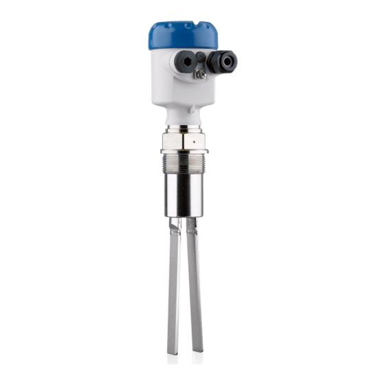
KROHNE OPTISWITCH 3100 C Handbook
Vibrating level switch
Hide thumbs
Also See for OPTISWITCH 3100 C:
- Operating instructions manual (32 pages) ,
- Handbook (32 pages) ,
- Technical data sheet (19 pages)
Table of Contents
Advertisement
Quick Links
Advertisement
Table of Contents

Related Manuals for KROHNE OPTISWITCH 3100 C


Summary of Contents for KROHNE OPTISWITCH 3100 C
- Page 1 OPTISWITCH 3100 C Handbook Vibrating Level Switch NAMUR...
-
Page 2: Table Of Contents
Maintenance ........................22 Rectify faults ........................22 Exchanging the electronics module ................23 Instrument repair ......................24 Dismount Dismounting steps......................25 Disposal ......................... 25 Supplement Technical data ........................ 26 Dimensions ........................29 Trademark ........................31 OPTISWITCH 3100 C • NAMUR... - Page 3 Contents Safety instructions for Ex areas Take note of the Ex specific safety instructions for Ex applications. These instructions are attached as documents to each instrument with Ex approval and are part of the operating instructions manual. Editing status: 2017-03-06 OPTISWITCH 3100 C • NAMUR...
-
Page 4: About This Document
Action This arrow indicates a single action. Sequence of actions Numbers set in front indicate successive steps in a procedure. Battery disposal This symbol indicates special information about the disposal of bat- teries and accumulators. OPTISWITCH 3100 C • NAMUR... -
Page 5: For Your Safety
During work on and with the device the required personal protective equipment must always be worn. Appropriate use The OPTISWITCH 3100 C is a sensor for point level detection. You can find detailed information about the area of application in chapter "Product description". Operational reliability is ensured only if the instrument is properly used according to the specifications in the operating instructions manual as well as possible supplementary instructions. -
Page 6: Safety Label On The Instrument
EU conformity The device fulfils the legal requirements of the applicable EU guide- lines. By affixing the CE marking, we confirm successful testing of the product. SIL conformity OPTISWITCH 3100 C meets the requirements to the functional safety according to IEC 61508. Further information is available in the Safety Manual "OPTISWITCH 3XXX". Safety instructions for Ex areas Please note the Ex-specific safety information for installation and op- eration in Ex areas. These safety instructions are part of the operating instructions manual and come with the Ex-approved instruments. -
Page 7: Product Description
Principle of operation Application area OPTISWITCH 3100 C is a point level sensor with tuning fork for point level detection. It is designed for industrial use in all areas of process technology and is preferably used for bulk solids. -
Page 8: Adjustment
Solid detection in water If OPTISWITCH 3100 C was ordered for solids detection in water, the tuning fork is set to the density of water. In air or when immersed in water (density: 1 g/cm³/0.036 lbs/in), OPTISWITCH 3100 C signals "uncovered". - Page 9 Protected against solar radiation • Avoiding mechanical shock and vibration • Storage and transport Storage and transport temperature see chapter "Supplement - temperature Technical data - Ambient conditions" • Relative humidity 20 … 85 % OPTISWITCH 3100 C • NAMUR...
-
Page 10: Mounting
You can find the specifications in chapter "Technical data" and on the nameplate. Switching point In general, OPTISWITCH 3100 C can be installed in any position. The instrument only has to be mounted in such a way that the vibrating element is at the height of the desired switching point. -
Page 11: Mounting Instructions
The vibrating element should protrude into the vessel to avoid buildup. For that reason, avoid using mounting bosses for flanges and screwed fittings. This applies particularly to use with adhesive products. Filling opening Mount the instrument in such a way that the tuning fork does not protrude directly into the filling stream. 20° Fig. 3: Horizontal installation Protective sheet Concave protective sheet for abrasive solids OPTISWITCH 3100 C • NAMUR... - Page 12 Fig. 4: Horizontal mounting Inflowing medium If OPTISWITCH 3100 C is mounted in the filling stream, unwanted false measurement signals can be generated. For this reason, mount OPTISWITCH 3100 C at a position in the vessel where no disturbanc- es, e.g. from filling openings, agitators, etc., can occur. Product flow To make sure the tuning fork of OPTISWITCH 3100 C generates as little resistance as possible to product flow, mount the sensor so that the surfaces are parallel to the product movement.
- Page 13 Fig. 6: Horizontal installation - marking Marking on top with screwed version Baffle protection against In applications such as grit chambers or settling basins for coarse falling rocks sediments, the vibrating element must be protected against damage with a suitable baffle. This baffle must be manufactured by you. OPTISWITCH 3100 C • NAMUR...
- Page 14 4 Mounting > 125 mm (> 5") Fig. 7: Baffle for protection against mechanical damage OPTISWITCH 3100 C • NAMUR...
-
Page 15: Connecting To Power Supply
With Ex instruments, the housing cover may only be opened if there is no explosive atmosphere present. Proceed as follows: 1. Unscrew the housing lid 2. Loosen compression nut of the cable gland and remove blind plug OPTISWITCH 3100 C • NAMUR... -
Page 16: Wiring Plan, Single Chamber Housing
10. If necessary, carry out a fresh adjustment 11. Screw the housing lid back on The electrical connection is finished. Wiring plan, single chamber housing The following illustrations apply to the non-Ex as well as to the Ex-d version. OPTISWITCH 3100 C • NAMUR... - Page 17 In shipping condition, terminals 3 and 4 are bridged. For additional information see "Recurring function test". 1 2 3 4 Fig. 11: Wiring plan - External simulation key 1 NAMUR amplifier Bridge External simulation key OPTISWITCH 3100 C • NAMUR...
-
Page 18: Setup
(1) It is already preset and must only be modified in special cases. By default, the potentiometer of OPTISWITCH 3100 C is set to the right stop (> 0.02 g/cm³ or 0.0008 lbs/in³). In case of very light-weight solids, turn the potentiometer to the left stop (> 0.008 g/cm³ or 0.0003 lbs/in³). -
Page 19: Function Table
• dark = Low current ≤ 1.0 mA • yellow (flashing) = Failure ≤ 1.0 mA Function table Level switch OPTISWITCH 3100 C The following table provides an overview of the switching conditions depending on the set mode and the level. Note: The mode setting on the NAMUR amplifier must be selected in such a way that the switching output takes on safe state in case of failure (I ≤ 1 mA). -
Page 20: Proof Test (Sil)
NAMUR electronics module WE60N. For this purpose, the switching delay must be set to 0.5 s. OPTISWITCH 3100 C has an integrated simulation key. The simulation key is lowered on the electronics module. Push the simulation key for > 2 seconds. - Page 21 (1.5 s ±0.5 s) 3. Return to the actual operating con- dition You can carry out the function test with the stated current values also directly with a safety PLC or a process control system. OPTISWITCH 3100 C • NAMUR...
-
Page 22: Maintenance And Fault Rectification
Exchange the instrument or send it in for repair Reaction after fault recti- Depending on the reason for the fault and the measures taken, the fication steps described in chapter "Set up" may have to be carried out again. OPTISWITCH 3100 C • NAMUR... -
Page 23: Exchanging The Electronics Module
9. Insert the electronics module carefully. Make sure that the plug is in the correct position. 10. Screw in and tighten the two holding screws with a screwdriver (Torx size T10 or Phillips 4) 11. Insert the wire ends into the open terminals according to the wir- ing plan OPTISWITCH 3100 C • NAMUR... -
Page 24: Instrument Repair
By doing this you help us carry out the repair quickly and without hav- ing to call back for needed information. • Print and fill out one form per instrument • Clean the instrument and pack it damage-proof • Attach the completed form and possibly also a safety data sheet to the instrument OPTISWITCH 3100 C • NAMUR... -
Page 25: Dismount
WEEE directive. Correct disposal avoids negative effects on humans and the environ- ment and ensures recycling of useful raw materials. Materials: see chapter "Technical data" If you have no way to dispose of the old instrument properly, please contact us concerning return and disposal. OPTISWITCH 3100 C • NAMUR... -
Page 26: Supplement
Ʋ Pipe thread, conical (ASME B1.20.1) 1½ NPT Instrument weight (depending on pro- 0.8 … 4 kg (0.18 … 8.82 lbs) cess fitting) Max. lateral load 600 N (135 lbf) Fig. 30: Max. lateral load alongside fork side (narrow fork side) OPTISWITCH 3100 C • NAMUR... - Page 27 Measured variable Limit level of solids Process pressure -1 … 25 bar/-100 … 2500 kPa (-14.5 … 363 psig) OPTISWITCH 3100 C of 316L -50 … +150 °C (-58 … +302 °F) Process temperature (thread or flange -50 … +250 °C (-58 … +482 °F)
- Page 28 0.02 … 0.1 g/cm³ (0.0007 … 0.036 lbs/in³) tion Simulation key simulation of a line break between sensor and process- ing unit Depending on the version M12 x 1, according to ISO 4400, Harting, 7/8" FF. OPTISWITCH 3100 C • NAMUR...
-
Page 29: Dimensions
ø 77mm (2.72") ø 84mm ø 77mm (3.03") (3.31") (3.03") M20x1,5/ M20x1,5/ M20x1,5/ M20x1,5 ½ NPT ½ NPT ½ NPT Fig. 32: Housing versions Plastic single chamber Stainless steel single chamber Aluminium - single chamber OPTISWITCH 3100 C • NAMUR... - Page 30 9 Supplement G1½ ø 43 mm (1.69") Fig. 33: OPTISWITCH 3100 C, threaded version G1½ (DIN ISO 228/1) ø 34 mm (1.34") Fig. 34: Temperature adapter OPTISWITCH 3100 C • NAMUR...
-
Page 31: Trademark
9 Supplement Trademark All the brands as well as trade and company names used are property of their lawful proprietor/ originator. OPTISWITCH 3100 C • NAMUR... - Page 32 Products and systems for the oil and gas industry • KROHNE Messtechnick GmbH & Co. KG Ludwig-Krohne-Straße 5 D-47058 Duisburg Tel.: +49 (0) 203 301 0 Tel.: +49 (0) 203 301 10389 info@krohne.de The current list of all KROHNE contacts and addresses can be found at: www.krohne.com...
Need help?
Do you have a question about the OPTISWITCH 3100 C and is the answer not in the manual?
Questions and answers