Advertisement
Quick Links
Owner's Manual
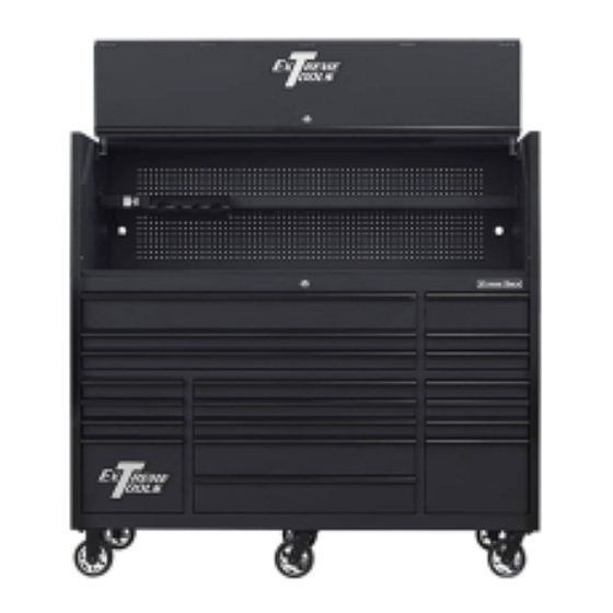
RX Series
72" W x 25"D Extreme Power Workstation Hutch
and 19 Drawer Roller Cabinet Combination
Models:
RX7220HR 72"W x 25"D x 69.25"H
Extreme Tools, Inc.
740 Frontenac Road
Naperville, Illinois 60563
Sales@extremetools.net
630.369.9303
www.ExtremeTools.com
Advertisement

Related Manuals for Extreme Tools RX Series


Summary of Contents for Extreme Tools RX Series
- Page 1 Owner’s Manual RX Series 72” W x 25”D Extreme Power Workstation Hutch and 19 Drawer Roller Cabinet Combination Models: RX7220HR 72”W x 25”D x 69.25”H Extreme Tools, Inc. 740 Frontenac Road Naperville, Illinois 60563 Sales@extremetools.net 630.369.9303 www.ExtremeTools.com...
- Page 2 (30” Deep Model Only)
- Page 3 RX722501HC Hutch Parts List ITEM # PART NUMBER DESCRIPTION QTY. Z-7225HC-01 BK 7225 Hutch Top-Back panel, BK Z-7225HC-01 BL 7225 Hutch Top-Back panel, BL Z-7225HC-01 GN 7225 Hutch Top-Back panel, GN Z-7225HC-01 MB 7225 Hutch Top-Back panel, MB Z-7225HC-01 OR 7225 Hutch Top-Back panel, OR ZRB-10 OD Rubber bumper, 10 mm OD...
- Page 4 RX722501HC Hutch Parts List continued ITEM # PART NUMBER DESCRIPTION QTY. ZM6SCSH-35 M6 x 35 mm Socket Head Screw, for RX/DX HC door hinge ZM8WAFT-BK M8 flat washer, Black ZM8WAFT-BL M8 flat washer, Blue ZM8WAFT-GN M8 flat washer, Green ZM8WAFT-MK M8 flat washer, Matte Black ZM8WAFT-OR M8 flat washer, Orange...
- Page 5 Roller Cabinet Parts List RX722519RC - X 150 lbs. Slides Replacement keys may be ordered using the code that appears on the face of the lock. To order replacement parts, have the part number, tool box color and quantity ready. If under warranty, the serial number is REQUIRED to get replacement parts.
- Page 6 RX7225,5525RC-X Side Push Handle Tubular, 483mm, Steel, Blue (19"MHD) 13 Z-LGL Extreme Tools Logo 14 Z-LGS Extreme Tools name plate 15 ZTRR979C RX72,55RC Ver�cal Side Trim, 979 mm, Polished Anodized Chrome 15 ZTRR979K RX72,55RC Ver�cal Side Trim, 979 mm, Polished Anodized Black 15 ZTRR979R RX72,55RC Ver�cal Side Trim, 979 mm, Polished Anodized Red...
- Page 7 RX72,55RC Quick Release Drawer Pull, 399 mm DDT, Polished Anodized Blue 20 ZDPRQ399K RX72,55RC Quick Release Drawer Pull, 399 mm DDT, Polished Anodized Black 21 ZM6SCHX-15 RX series drawer handle screws 23 ZDL375X559 PVC Drawer liner, small, 375x559, PVC, Black 24 ZDL839X559 PVC...
- Page 8 Step 0: PRIOR TO ASSEMBLY Adjustment Check fit of Splicer Post Screw BEFORE attaching to Side a. BEFORE ASSEMBLING SIDE PANEL, check the tightness of Panel. Adjust as necessary the Splicer Posts by inserting them into the side trim. The fit using Adjustment Screw.
- Page 9 Step 2: Install Side Panels on Roller Cabinet a. Remove plastic end caps from the top of the trim located at the front corners of the roller cabinet. b. Slide end of splicer channel into opening where plastic end cap was located until side panel rests on top of MDF/Stainless Steel Top.
- Page 10 Step 3: Secure Side Panels a. Loosely install one Hold-Down Bracket (#14) on each side using one flat washer (#16) and one M8 bolt (#15) for each side. If attaching the side locker or side box, do not use Hold-Down Bracket on that side.
- Page 11 Step 4: Install Adjustable Shelf a. Determine the desired height for the Adjustable Shelf. Pre-thread (2) screws (#11) about halfway in on left-hand and right-hand sides. b. Locate the (2) open slots on each side of the shelf. Line up the open slots with the (4) threaded screws that were installed in Step 5d.
- Page 12 Step 5: Install Back Panel a. Pull MDF board/Stainless Steel Top forward approximately 1/8” from Back Raised Edge (aka: Fence Rail.) b. Lift Back Panel into place behind the two side panels. (BACK PANEL is HEAVY and requires 2 people to place!) Slide the bottom edge of the Back Panel between the MDF/Stainless Steel Top and rear fence rail of roller cabinet.
- Page 13 Step 6: Secure Back Panel c. Locate (2) threaded inserts on the back of the shelf. From the back of the Back Panel, insert (2) screws through the back of the pegboard and through the threaded inserts of the shelf and tighten. d.
- Page 14 Step 7: Attach Spacer Panel (for 30” Deep Model ONLY) a. After the back panel has been installed, attach the spacer panel to the top section of the back panel. Use (6) M6x12mm pan head screws to secure spacer panel to top section of back panel. Use (4) additional screws to attach the spacer to the top of both side panels.
- Page 15 Step 8: Attach Gas Struts to Lid a. Lay the lid down on packaging material so that the front of the lid is face down. Use a soft surface or packaging material under the lid so that it does not get scratched or damaged. b.
- Page 16 Step 10: Secure Lid to Body of Hutch - may require assistance of another adult a. Position the top front panel so that it rests on top of the side and back panels and holes on lid and side panels are aligned as shown below. b.
- Page 17 Step 11: Secure Gas Strut to Side of Hutch a. Lift top/front panel so that the unattached ball joint on the gas strut is lined up with the rivet nut hole on the side panel. b. Hand-tighen the male stud into the rivet nut opening. Strut must be fully engaged with the ball stud.
- Page 18 Step 12: Re-Attach Front Panel to Lid a. Lift front panel into place to re-attach to lid. Align the hinges on the top panel with the hinges on the lid and slide into place. Smooth side of lid should face out - panel stiffener should be on the inside.
- Page 19 Step 12: Final Hutch Details a. If you did not install the Hold Down Bracket in Step 3, then do so now. b. Securely tighten ALL screws and bolts!
-
Page 20: Operating Procedure
ROLLER CABINET ASSEMBLY Handle Installation Handle Installation NOTE: Assemble the handle first to make it easier to move the tool cabinet. NOTE: Assemble the handle first to make it easier to move the tool cabinet. Position the handle over the holes in the cabinet and attach with the provided (4) M6-1.0 x 15 SH screws. Position the handle over the holes in the cabinet and attach with the provided (4) M6-1.0 x 15 SH screws. - Page 21 SAFETY WARNING Do not attempt to lift the cabinet by its side handle using chains, ropes or lifting device. Side handle may fail resulting in personal injury or damage to the product! Use a forklift or similar lifting device with forks placed under the bottom of the tool box to move if tool box cannot be moved by two people. Close the drawers and lock the tool box before moving this product! If drawers are not locked they could open and make the product unstable and tip which may cause personal injury or damage to the product.
Need help?
Do you have a question about the RX Series and is the answer not in the manual?
Questions and answers