Advertisement
Quick Links
Owner's Manual
Professional
Powder-Coated Steel Hutch and Roller Cabinet
Combination
Model:
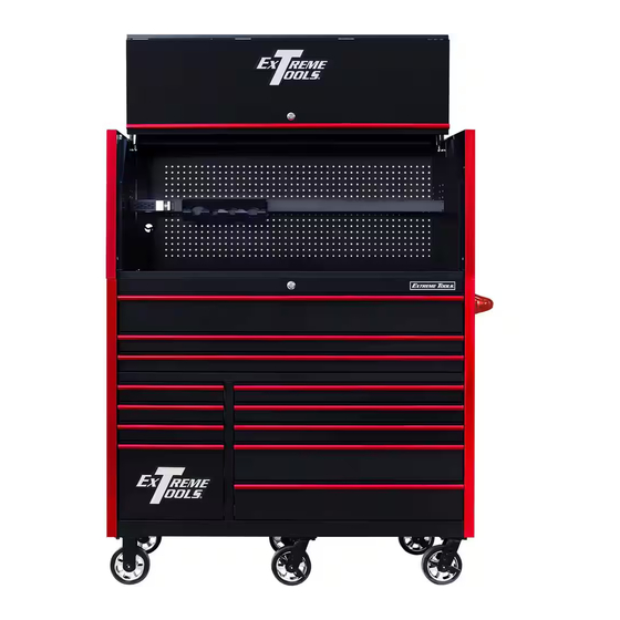
RX5513HR 55in W x 25in D x 69.25in H
Extreme Power Workstation Hutch Assembly instructions
apply to all RX Series 55 in. and 72 in. models
(Assembly instructions shown using 72 in. model diagrams)
Extreme Tools, Inc.
740 Frontenac Road
Naperville, Illinois 60563
Sales@extremetools.net
630.369.9303
www.ExtremeTools.com
©2023
Advertisement

Related Manuals for Extreme Tools RX5513HR


Summary of Contents for Extreme Tools RX5513HR
- Page 1 Powder-Coated Steel Hutch and Roller Cabinet Combination Model: RX5513HR 55in W x 25in D x 69.25in H Extreme Power Workstation Hutch Assembly instructions apply to all RX Series 55 in. and 72 in. models (Assembly instructions shown using 72 in. model diagrams) Extreme Tools, Inc.
- Page 2 Extreme Power Workstation Hutch Parts List RX5513HR (30” Deep Model Only)
- Page 3 Extreme Power Workstation Hutch Parts List RX5513HR ITEM # PART NUMBER DESCRIPTION Z-5525HC-01 BK 7225 Hutch Top-Back panel, BK Z-5525HC-01 BL 7225 Hutch Top-Back panel, BL Z-5525HC-01 GN 7225 Hutch Top-Back panel, GN Z-5525HC-01 MB 7225 Hutch Top-Back panel, MB...
- Page 4 Extreme Power Workstation Hutch Parts List Continued RX5513HR ITEM # PART NUMBER DESCRIPTION ZM6SCSH-35 M6 x 35 mm Socket Head Screw, for RX/DX HC door hinge ZM8WAFT-BK M8 flat washer, Black ZM8WAFT-BL M8 flat washer, Blue ZM8WAFT-GN M8 flat washer, Green...
- Page 5 55 inch Roller Cabinet 150 lbs slides Parts List RX5513HR Replacement keys may be ordered using the code that appears on the face of the lock. To order replacement parts, have the part number, tool box color and quantity ready. If under warranty, the serial number is REQUIRED to get replacement parts.
- Page 6 ZDL839X559 PVC Drawer liner, med, 839x559, PVC, Black ZDL375X559 PVC Drawer liner, small, 375x559, PVC, Black ZCA62MR 6X2" Mag Wheel Rigid Caster, 900 Lb Ra�ng ZCA62MS 6X2" Mag Wheel Swivel Caster with Brake, 900 Lb Ra�ng Z-LGS Extreme Tools name plate...
- Page 7 55 inch Roller Cabinet 150 lbs slides Parts List Continued RX5513HR Item # Part number Descrip�ons Qty. ZHDR483TSK RX7225,5525RC-X Side Push Handle Tubular, 483mm, Steel, Black (19"MHD) ZHDR483TSU RX7225,5525RC-X Side Push Handle Tubular, 483mm, Steel, Blue (19"MHD) ZHDR483TSR RX7225,5525RC-X Side Push Handle Tubular, 483mm, Steel, Red (19"MHD)
- Page 8 Step 0: PRIOR TO ASSEMBLY Adjustment Check fit of Splicer Post Screw BEFORE attaching to Side a. BEFORE ASSEMBLING SIDE PANEL, check the tightness of Panel. Adjust as necessary the Splicer Posts by inserting them into the side trim. The fit using Adjustment Screw.
- Page 9 Step 2: Install Side Panels on Roller Cabinet a. Remove plastic end caps from the top of the trim located at the front corners of the roller cabinet. b. Slide end of splicer channel into opening where plastic end cap was located until side panel rests on top of MDF/Stainless Steel Top.
- Page 10 Step 3: Secure Side Panels a. Loosely install one Hold-Down Bracket (#14) on each side using one flat washer (#16) and one M8 bolt (#15) for each side. If attaching the side locker or side box, do not use Hold-Down Bracket on that side.
- Page 11 Step 4: Install Adjustable Shelf a. Determine the desired height for the Adjustable Shelf. Pre-thread (2) screws (#11) about halfway in on left-hand and right-hand sides. b. Locate the (2) open slots on each side of the shelf. Line up the open slots with the (4) threaded screws that were installed in Step 5d.
- Page 12 Step 5: Install Back Panel a. Pull MDF board/Stainless Steel Top forward approximately 1/8” from Back Raised Edge (aka: Fence Rail.) b. Lift Back Panel into place behind the two side panels. (BACK PANEL is HEAVY and requires 2 people to place!) Slide the bottom edge of the Back Panel between the MDF/Stainless Steel Top and rear fence rail of roller cabinet.
- Page 13 Step 6: Secure Back Panel c. Locate (2) threaded inserts on the back of the shelf. From the back of the Back Panel, insert (2) screws through the back of the pegboard and through the threaded inserts of the shelf and tighten. d.
- Page 14 Step 7: Attach Gas Struts to Lid a. Lay the lid down on packaging material so that the front of the lid is face down. Use a soft surface or packaging material under the lid so that it does not get scratched or damaged. b.
- Page 15 Step 8: Secure Lid to Body of Hutch - may require assistance of another adult a. Position the top front panel so that it rests on top of the side and back panels and holes on lid and side panels are aligned as shown below. b.
- Page 16 Step 9: Secure Gas Strut to Side of Hutch a. Lift top/front panel so that the unattached ball joint on the gas strut is lined up with the rivet nut hole on the side panel. b. Hand-tighen the male stud into the rivet nut opening. Strut must be fully engaged with the ball stud.
- Page 17 Step 10: Re-Attach Front Panel to Lid a. Lift front panel into place to re-attach to lid. Align the hinges on the top panel with the hinges on the lid and slide into place. Smooth side of lid should face out - panel stiffener should be on the inside.
-
Page 18: Step 11: Final Details
Step 11: Final Details a. If you did not install the Hold Down Bracket in Step 3, then do so now. b. Securely tighten ALL screws and bolts! FULLY ASSEMBLED RX SERIES 55 inch HUTCH shown on RX SERIES 55 inch ROLLER CABINET...
Need help?
Do you have a question about the RX5513HR and is the answer not in the manual?
Questions and answers