Advertisement
Quick Links
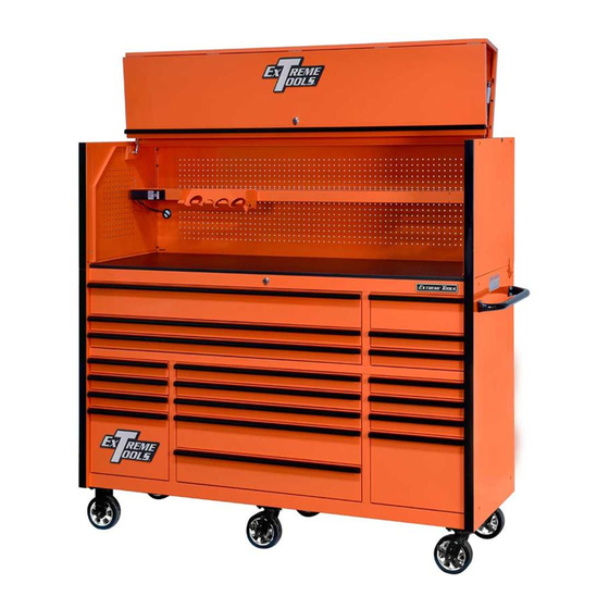
Owner's Manual
Professional
Powder-Coated Steel Hutches
72 inch Steel Top Hutch
shown on RX Series Roller Cabinet
Models:
RX722501HC 72"W x 25"D
RX723001HC 72"W x 30"D
RX552501HC 55"W x 25"D
Extreme Tools, Inc.
740 Frontenac Road
Naperville, Illinois 60563
Sales@extremetools.net
630.369.9303
www.ExtremeTools.com
Advertisement

Related Manuals for Extreme Tools RX722501HC


Summary of Contents for Extreme Tools RX722501HC
- Page 1 Owner’s Manual Professional Powder-Coated Steel Hutches 72 inch Steel Top Hutch shown on RX Series Roller Cabinet Models: RX722501HC 72”W x 25”D RX723001HC 72”W x 30”D RX552501HC 55”W x 25”D Extreme Tools, Inc. 740 Frontenac Road Naperville, Illinois 60563 Sales@extremetools.net 630.369.9303...
- Page 2 (30” Deep Model Only)
- Page 3 RX722501HC Parts List ITEM # PART NUMBER DESCRIPTION QTY. Z-7225HC-01 BK 7225 Hutch Top-Back panel, BK Z-7225HC-01 BL 7225 Hutch Top-Back panel, BL Z-7225HC-01 GN 7225 Hutch Top-Back panel, GN Z-7225HC-01 MB 7225 Hutch Top-Back panel, MB Z-7225HC-01 OR 7225 Hutch Top-Back panel, OR...
- Page 4 RX722501HC Parts List ITEM # PART NUMBER DESCRIPTION QTY. ZM6SCSH-35 M6 x 35 mm Socket Head Screw, for RX/DX HC door hinge ZM8WAFT-BK M8 flat washer, Black ZM8WAFT-BL M8 flat washer, Blue ZM8WAFT-GN M8 flat washer, Green ZM8WAFT-MK M8 flat washer, Matte Black...
- Page 5 RX723001HC Parts List ITEM # PART NUMBER DESCRIPTION QTY. Z-7225HC-01 BK 7225 Hutch Top-Back panel, BK Z-7225HC-01 BL 7225 Hutch Top-Back panel, BL Z-7225HC-01 GN 7225 Hutch Top-Back panel, GN Z-7225HC-01 MB 7225 Hutch Top-Back panel, MB Z-7225HC-01 OR 7225 Hutch Top-Back panel, OR ZRB-10 OD Rubber bumper installed on lid panel, 10 mm OD Z-7230HC-02 KC...
- Page 6 RX723001HC Parts List ITEM # PART NUMBER DESCRIPTION QTY. Z-PS333032 POWER STRIP, 2.1A USBX2, 120VX3 ZM4SCPH-12 PAN HEAD M4 SCREWS, 12 MM LONG for power strip Z-7225HC-22 BK Hutch-RC Connecting Bracket for sides, BK Z-7225HC-22 BL Hutch-RC Connecting Bracket for sides, BL Z-7225HC-22 GN Hutch-RC Connecting Bracket for sides, GN Z-7225HC-22 MB...
- Page 7 RX552501HC Parts List ITEM # PART NUMBER DESCRIPTION Z-5525HC-01 BK 7225 Hutch Top-Back panel, BK Z-5525HC-01 BL 7225 Hutch Top-Back panel, BL Z-5525HC-01 GN 7225 Hutch Top-Back panel, GN Z-5525HC-01 MB 7225 Hutch Top-Back panel, MB Z-5525HC-01 OR 7225 Hutch Top-Back panel, OR Z-7225HC-02 KC RX 25"...
- Page 8 RX552501HC Parts List ITEM # PART NUMBER DESCRIPTION ZM6SCSH-35 M6 x 35 mm Socket Head Screw, for RX/DX HC door hinge ZM8WAFT-BK M8 flat washer, Black ZM8WAFT-BL M8 flat washer, Blue ZM8WAFT-GN M8 flat washer, Green ZM8WAFT-MK M8 flat washer, Matte Black ZM8WAFT-OR M8 flat washer, Orange ZM8SCHX-16 BK...
- Page 9 Step 0: PRIOR TO ASSEMBLY Adjustment Check fit of Splicer Post Screw BEFORE attaching to Side a. BEFORE ASSEMBLING SIDE PANEL, check the tightness of Panel. Adjust as necessary the Splicer Posts by inserting them into the side trim. The fit using Adjustment Screw.
- Page 10 Step 2: Install Side Panels on Roller Cabinet a. Remove plastic end caps from the top of the trim located at the front corners of the roller cabinet. b. Slide end of splicer channel into opening where plastic end cap was located until side panel rests on top of MDF/Stainless Steel Top.
- Page 11 Step 3: Secure Side Panels a. Loosely install one Hold-Down Bracket (#14) on each side using one flat washer (#16) and one M8 bolt (#15) for each side. If attaching the side locker or side box, do not use Hold-Down Bracket on that side.
- Page 12 Step 4: Install Adjustable Shelf a. Determine the desired height for the Adjustable Shelf. Pre-thread (2) screws (#11) about halfway in on left-hand and right-hand sides. b. Locate the (2) open slots on each side of the shelf. Line up the open slots with the (4) threaded screws that were installed in Step 5d.
- Page 13 Step 5: Install Back Panel a. Pull MDF board/Stainless Steel Top forward approximately 1/8” from Back Raised Edge (aka: Fence Rail.) b. Lift Back Panel into place behind the two side panels. (BACK PANEL is HEAVY and requires 2 people to place!) Slide the bottom edge of the Back Panel between the MDF/Stainless Steel Top and rear fence rail of roller cabinet.
- Page 14 Step 6: Secure Back Panel c. Locate (2) threaded inserts on the back of the shelf. From the back of the Back Panel, insert (2) screws through the back of the pegboard and through the threaded inserts of the shelf and tighten. d.
- Page 15 Step 7: Attach Spacer Panel (for 30” Deep Model ONLY) a. After the back panel has been installed, attach the spacer panel to the top section of the back panel. Use (6) M6x12mm pan head screws to secure spacer panel to top section of back panel. Use (4) additional screws to attach the spacer to the top of both side panels.
- Page 16 Step 8: Attach Gas Struts to Lid a. Lay the lid down on packaging material so that the front of the lid is face down. Use a soft surface or packaging material under the lid so that it does not get scratched or damaged. b.
- Page 17 Step 10: Secure Lid to Body of Hutch - may require assistance of another adult a. Position the top front panel so that it rests on top of the side and back panels and holes on lid and side panels are aligned as shown below. b.
- Page 18 Step 11: Secure Gas Strut to Side of Hutch a. Lift top/front panel so that the unattached ball joint on the gas strut is lined up with the rivet nut hole on the side panel. b. Hand-tighen the male stud into the rivet nut opening. Strut must be fully engaged with the ball stud.
- Page 19 Step 12: Re-Attach Front Panel to Lid a. Lift front panel into place to re-attach to lid. Align the hinges on the top panel with the hinges on the lid and slide into place. Smooth side of lid should face out - panel stiffener should be on the inside.
-
Page 20: Step 12: Final Details
Step 12: Final Details a. If you did not install the Hold Down Bracket in Step 3, then do so now. b. Securely tighten ALL screws and bolts! FULLY ASSEMBLED RX SERIES HUTCH shown on RX SERIES ROLLER CABINET...
Need help?
Do you have a question about the RX722501HC and is the answer not in the manual?
Questions and answers