Advertisement
Quick Links
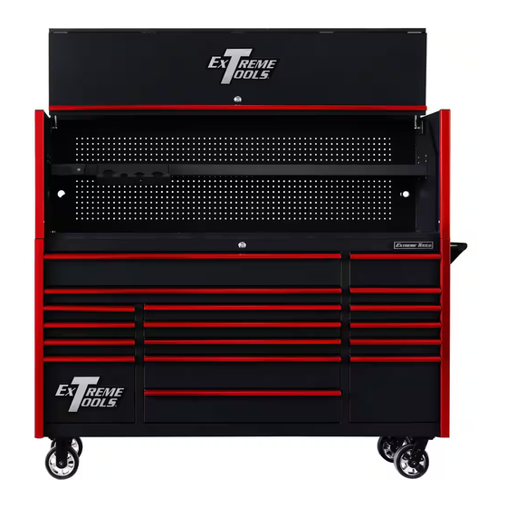
DX Series 72 in. W x 21 in. D x 65 in. H
Powder-Coated Steel Hutch
with Power Tool Rack Accessory
and
17-Drawer Roller Cabinet Combination
DX Series 72 in. Extreme Power Workstation & 17-Drawer Roller Cabinet
Combination Models:
DX722118HR
DX7218HR
Extreme Tools, Inc.
740 Frontenac Road
Naperville, Illinois 60563
630.369.9303
www.ExtremeTools.com
Sales@extremetools.net
CustomerService@extremetools.net
©2023
Advertisement

Related Manuals for Extreme Tools DX Series


Summary of Contents for Extreme Tools DX Series
- Page 1 DX Series 72 in. W x 21 in. D x 65 in. H Powder-Coated Steel Hutch with Power Tool Rack Accessory 17-Drawer Roller Cabinet Combination DX Series 72 in. Extreme Power Workstation & 17-Drawer Roller Cabinet Combination Models: DX722118HR DX7218HR Extreme Tools, Inc.
- Page 2 Extreme Power Workstation Hutch Parts for DX722101HC, DX7201HC Replacement keys may be ordered using the code that appears on the face of the lock. To order replacement parts, have the part number, tool box color and quantity ready. If under warranty, the serial number is REQUIRED to get replacement parts.
-
Page 3: Parts List
Extreme Power Workstation (DX722101HC, DX7201HC) PARTS LIST ITEM # PART NUMBER DESCRIPTION QTY. Z-7221HC-01 BK 7221 Hutch Top-Back panel, BK Z-7221HC-01 BL 7221 Hutch Top-Back panel, BL Z-7221HC-01 GN 7221 Hutch Top-Back panel, GN Z-7221HC-01 MB 7221 Hutch Top-Back panel, MB Z-7221HC-01 OR 7221 Hutch Top-Back panel, OR Z-7221HC-02 BK... - Page 4 Adjustable Power Tool Rack, Blue ACPTRGN Adjustable Power Tool Rack, Green ACPTRMB Adjustable Power Tool Rack, Ma�e Black ACPTROR Adjustable Power Tool Rack, Orange Extreme Tools Logo Z-LGL Z-BRJHOOKDXHC J hook bracket for moun�ng DX HC side panel to DXRC, *Not Shown on Drawing...
- Page 5 DX Series 72 in. 17-Drawer Roller Cabinet Parts List (DX722117RC, DX7217RC) shown Replacement keys may be ordered using the code that appears on the face of the lock. To order replacement parts, have the part number, tool box and drawer pull color and quantity ready.
- Page 6 DX Series 72 in. Roller Cabinet Parts List (DX722117RC, DX7217RC) Item Part number Descrip�on Z-BTM10X25SHH M10X25 Serrated Hex Head Bolt ZCA62MR 6X2" Mag Wheel Rigid Caster, 900 Lb Ra�ng ZCA62MS 6X2" Mag Wheel Swivel Caster with Brake, 900 Lb Ra�ng...
- Page 7 DX Series 72 in. Roller Cabinet Parts List Continued (DX722117RC, DX7217RC) Item Part number Descrip�on ZDRD398C2QWKU DX7221RC Drawer 398 mm Wide, 100 Lb Slides, Double Deep, Black with Blue Drawer ZDRD398C2QWKR DX7221RC Drawer 398 mm Wide, 100 Lb Slides, Double Deep, Black with Red Drawer...
-
Page 8: Operating Procedure
ASSEMBLY Handle Installation NOTE: Assemble the handle first to make it easier to move the tool cabinet. Position the handle over the holes in the cabinet and attach with the provided (4) M6 socket head screws. Tighten securely. OPERATING PROCEDURE Drawer Removal Pull drawer out so that it is almost fully extended. - Page 9 HUTCH ASSEMBLY INSTRUCTIONS STEP 1: Remove End Caps a. IMPORTANT! Engage the brakes on the casters of the roller cabinet! b. Remove plastic end caps from the top of the trim on the roller cabinet. c. Set aside to re-install later. STEP 2: Remove Trim from Side Panels a.
- Page 10 STEP 3: Install Left & Right Side Panel Assembly a. Insert the “J” end of the J-Connector into the rectangular opening at the top of the trim of the roller cabinet where the end cap was removed. The “J” end of the connector should be facing the body of the tool box.
- Page 11 STEP 4: Install Adjustable Shelf a. Determine the desired height for the Adjustable Shelf. Pre-thread (2) screws (#11) about halfway in on left-hand and right-hand sides. b. Locate the (2) cutouts on each side of the shelf. Line up the open slots with the (4) threaded screws that were installed in Step 5d.
- Page 12 STEP 5: Install Back Panel a. Pull MDF board/Stainless Steel Top forward approximately 1/8” from Back Raised Edge (aka: Fence Rail.) b. Lift Back Panel into place behind the two side panels. (BACK PANEL is HEAVY and requires 2 people to place!) Slide the bottom edge of the Back Panel between the MDF/Stainless Steel Top and rear fence rail of roller cabinet.
- Page 13 STEP 6: Secure Shelf to Back Panel a. Locate (2) threaded inserts on the back of the shelf. From the back of the Back Panel, insert (2) screws through the back of the pegboard and and through the threaded inserts of the shelf and tighten.
- Page 14 STEP 7: Attach Gas Struts to Lid a. Lay the lid down on packaging material so that the front of the lid is face down. Use a soft surface or packaging material under the lid so that it does not get scratched or damaged. b.
- Page 15 STEP 8: Secure Lid to Body of Hutch - may require assistance of another adult a. Position the top front panel so that it rests on top of the side and back panels and holes on lid and side panels are aligned as shown below. b.
- Page 16 STEP 9: Secure Gas Strut to Side of Hutch a. Lift top/front panel so that the unattached ball joint on the gas strut is lined up with the rivet nut hole on the side panel. b. Hand-tighen the male stud into the rivet nut opening. Strut must be fully engaged with the ball stud.
- Page 17 STEP 10: Re-Attach Front Panel to Lid a. Lift front panel into place to re-attach to lid. Align the hinges on the top panel with the hinges on the lid and slide into place. Smooth side of lid should face out - panel stiffener should be on the inside.
- Page 18 Step 11: Final Assembly a. Re-attach the Vertical Trim Covers to the front of the Hutch Side Panels. b. Insert the End Caps into the openings at the top of the Vertical Trim Covers. c. Use the supplied hardware to attach the Power Strip on either the right or left side of the face of the adjustable shelf.
- Page 19 DX Series 72 in. Extreme Power Workstation Hutch ® shown assembled on Roller Cabinet...
-
Page 20: Maintenance
MAINTENANCE Lubricate the casters once a year with high quality ball bearing grease. Lubricate the slides twice a year with high quality, petroleum-based lubricant. This may be required more often if operating the tool box in colder climates. Use mild detergent and water to clean drawer fronts, drawer trim and other surfaces. Grease and oil can be removed with standard, non-abrasive, non-flammable cleaning products.
Need help?
Do you have a question about the DX Series and is the answer not in the manual?
Questions and answers