Table of Contents
Advertisement
Quick Links
Advertisement
Table of Contents

Related Manuals for Racelogic VBOX3i


Summary of Contents for Racelogic VBOX3i
- Page 1 VBOX3i 100Hz GPS Data Logger User Guide...
- Page 2 VB3i MANUAL This page intentionally left blank Page | 2 22 May 2014...
-
Page 3: Table Of Contents
CAN pass through ................................. 15 CANVEL ..................................16 Dynamic modes ................................16 USB....................................16 Bluetooth ..................................17 Pairing your computer with the VBOX3i ............................17 Audio ..................................... 17 Recording a sound wav .................................17 VBO file format ................................17 VBOXTools software ........................ 18 Software installation .............................. - Page 4 Using IMU as CAN module ......................22 Required equipment ..............................22 Setup ..................................... 22 Mounting the IMU ........................23 Troubleshooting ........................24 VBOX3i V3 specification ......................25 Connection data ........................26 Analogue input connector V1/V2....................27 Analogue input connector V3 ....................27 CAN output ..........................28 Upgrading VBOX3i firmware .....................
-
Page 5: Ec Declaration Of Conformity
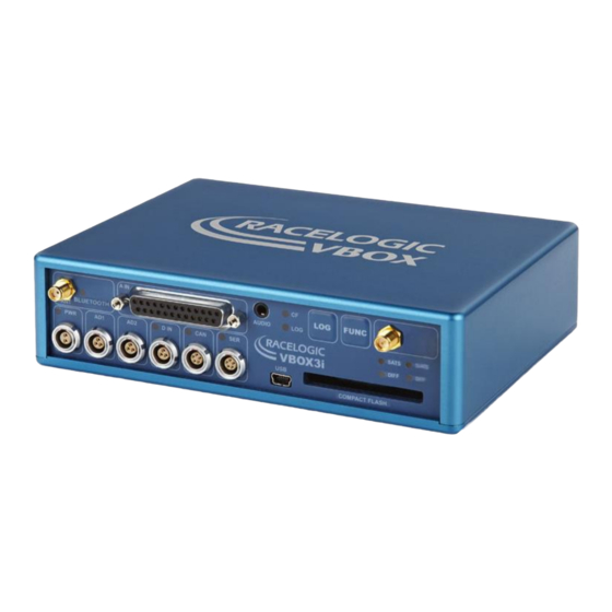
GPS data logging system from Racelogic. Using a powerful GPS engine, the VBOX3i can log GPS and other data at 100Hz. The logged data is stored directly onto a compact flash card for easy transfer to a PC. -
Page 6: Inputs/Outputs
VB3i MANUAL Inputs/outputs Standard inventory Description RL Part # Description Racelogic Part # VBOX3i data logger RLVB3I-V2 Serial PC cable RLCAB001 Mains power supply RLVBACS020 25 Way D connector ADC25IPCON Cigar lighter power supply RLCAB010L VBOX3i audio headset RLACS120 GPS magnetic antenna... -
Page 7: Quickstart Guide
If the VBOX3i has not been used for a long time or if it was last used many miles from its current location, it may take time to find satellite lock. -
Page 8: Operation
VBOX3i will look for a connected GPS antenna and automatically adjust its gain for optimum performance. Buttons VBOX3i has two membrane buttons on the front panel, LOG and FUNC. LOG is used to start and stop logging to the compact flash card, and FUNC is used to switch between two sample rates, 100Hz and 20Hz. -
Page 9: Logging
Without ‘log continuously’ ticked then the VBOX will only log data to the CF card when it detects speed >0.5Km/h. Advanced: The advanced logging option on the VBOX3i allows any of the logged data channels to be used to trigger the logging on the VBOX. -
Page 10: Diff/Dgps
The VBOX3i stores logged data onto CF cards. The CF cards available from Racelogic are already optimised for use on the VBOX3i and as such do not need formatting before use. Should the CF Card need formatting due to card errors it can be done through Windows, as the VBOX3i supports the following format type: ... -
Page 11: Gps Antenna
GPS antenna The GPS antenna supplied with the VBOX3i is a 5V active antenna. For the best possible signal quality, it is important to maintain a clean connection between the antenna and the VBOX3i. Before fixing the antenna to the VBOX3i, ensure that there are no dust particles in either connector. -
Page 12: Analogue And Digital Outputs (Ad1 & Ad2)
Digital inputs (D IN) The ‘D IN’ connector contains the two digital inputs for the VBOX3i. Digital input 1 is also referred to as the brake trigger input. This input is connected to an event capture input on the GPS engine. This captures precisely the trigger event time (10nS resolution) for use in brake distance calculation. -
Page 13: Analogue Inputs (A In)
VB3i MANUAL Analogue inputs (A IN) The VBOX3i contains four differential 24bit analogue input channels with a maximum sample rate of 100Hz. Each channel has its own dedicated analogue to digital (A/D) converter with all four channels being sampled synchronously to each other. -
Page 14: Rs232 Serial / Can
RS232 serial / CAN VBOX3i is equipped with 2 CAN Bus interfaces and 2 RS232 serial ports. The primary RS232 port is used for all communication between the VBOX and laptop PC. The primary port is marked RS232 on the VBOX3i front panel. The primary RS232 port is able to transmit live data from the VBOX to the PC for viewing and performing real-time tests. -
Page 15: Vci Can Input (Vehicle Can Interface)
VCI CAN input (vehicle CAN interface) The VBOX3i can log up to 16 user defined CAN bus signals on CAN port B. Configuration is performed using the VCI modules tab under log channels in VBOXTools software setup window. CAN signal parameters can be entered manually by the user or imported directly from a CAN database (.DBC) file if available. -
Page 16: Canvel
These drivers can also be found on the actual VBOXTools installation CD. When you connect you powered up VBOX3i to your PC with the supplied RLVBCAB066 USB A to USB mini lead your PC will recognise the presence of new hardware and open the typical Windows install window for new hardware. Follow the on screen prompts and point the Windows installation to the location of your drivers. -
Page 17: Bluetooth
The VBOX3i will need the Bluetooth antenna connected and the computer will require a Bluetooth module or dongle to establish a virtual connection. VBOX3i will connect to the computer via SPP (serial port profile) this can be done as a secure or unsecure connection. -
Page 18: Vboxtools Software
There are two available Basestation options: 40cm positional accuracy: If the VBOX3i is used with a RTCM-V2 enabled Basestation then the positional accuracy is increased to 40cm 95% CEP. The height accuracy is improved to 1M 95%CEP 2cm positional accuracy: If the VBOX3i has an RTK upgrade option installed and is used with a RLVBBS4RG then the positional accuracy is increased to 2cm. -
Page 19: Imu Integration
VB3i MANUAL IMU integration Required equipment IMU04 IMU03 VB3i-V3 VB3i (works with all VB3i units) IMU04 IMU03 VBOX Tools VBOX Tools RLCAB119 VBOX – IMU connecting cable RLCAB005-CS VBOX – IMU connecting cable RLCAB001 / RLCAB066-2 – VB3i PC connection cable RLCAB001 / RLCAB066-2 –... -
Page 20: Hardware Setup
VB3i MANUAL Hardware Setup Initialisation When using IMU integration, an initialisation phase is required when the IMU is first connected to the VBOX after being set up. This will be run through automatically after the VBOX has successfully gained satellite lock. When the IMU LED on VB3i front panel has turned a flashing green, the initialisation is complete. -
Page 21: Kalman Filter Calibration - High Dynamic Tests
VB3i MANUAL Kalman Filter calibration – High dynamic tests To produce the optimum level of accuracy as quickly as possible, a series of specific manoeuvres can be performed that help the Kalman filter characterise the outputs from the IMU. Note that while this is recommended, it is not completely necessary as the Kalman filter will have enough data to achieve accurate results within a few minutes of normal dynamic driving (including left and right hand turns, braking and accelerating). -
Page 22: Additional Imu Channels (Imu04 Only)
VB3i MANUAL Additional IMU channels (IMU04 only) IMU Attitude When using IMU04 integration with a VB3i-V3, there are three IMU attitude channels which can be logged. These body angle channels are heading, pitch and roll calculated from IMU derived data. RMS Channels These four channels are for diagnostic purposes only and cannot be turned on or off. -
Page 23: Mounting The Imu
VB3i MANUAL Mounting the IMU The IMU should be mounted rigidly to the vehicle mid-way along the wheelbase. Try to position the unit as close as possible to the centre of the vehicle, making sure it is mounted in the direction of travel - as shown in the image above. -
Page 24: Troubleshooting
No communication with PC If the red LED on the front of the VBOX3i is not illuminated then there is no power to the unit; check that battery contains adequate charge or, if using a cigar lighter, check internal cigar lighter fuse. -
Page 25: Vbox3I V3 Specification
VB3i MANUAL VBOX3i V3 specification Velocity Distance Accuracy 0.1 Km/h (averaged over Accuracy 0.05% (<50cm per Km) 4 samples) Units Km/h or Mph Units Metres / Feet Update rate 100 Hz Update rate 100Hz Maximum velocity 1000 Mph Resolution Minimum velocity 0.1 Km/h... -
Page 26: Connection Data
VB3i MANUAL Connection data Front View of VBOX3i V1 Front View of VBOX3i V2/V3 3 PIN LEMO socket 5 PIN LEMO socket 2 PIN LEMO socket Connector 1 POWER Type Lemo 2 pin In/Out Description Range Power + 7V to 30V... -
Page 27: Analogue Input Connector V1/V2
VB3i MANUAL Analogue input connector V1/V2 View of Socket on VBOX 3i Connector: Analogue Type: Sub-D 25-way Socket Connector: Type: Sub-D 25-way Socket Analogue In/Out Description Range In/Out Description Range Channel 1 + Vbatt Equal to Input Voltage. 100mA Channel 1 - Channel 2 + 5 V Out 5V ±2%. -
Page 28: Can Output
VB3i MANUAL CAN output The VBOX3i has a CAN output which is present on the 5-way connector output; Data format: Motorola; Baud rate: 500Kb/s. Format Motorola ID** Data Bytes 0x301 (1) Sats in (2) Time since midnight UTC (3) Position – Latitude MMMM.MMMMM... -
Page 29: Upgrading Vbox3I Firmware
Once the upgrade is complete the upgrade file will be erased and a report file will be generated. If the upgrade fails for any reason the upgrade file remains on the card and the VBOX3i retains the previous version of firmware.
Need help?
Do you have a question about the VBOX3i and is the answer not in the manual?
Questions and answers