Table of Contents
Advertisement
Quick Links
Advertisement
Table of Contents

Related Manuals for E+E Elektronik EE850


Summary of Contents for E+E Elektronik EE850
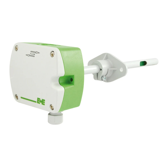
- Page 1 User Manual EE850 , Humidity and Temperature Duct Sensor...
-
Page 2: Table Of Contents
Calibration and Adjustment ........................14 7.1.1. Definitions ............................... 14 7.1.2. , T and RH Calibration and Adjustment ..................... 15 7.1.3. Calibration and Adjustment at E+E Elektronik ....................15 7.1.4. Calibration and Adjustment by the User ......................15 Repairs ..............................16 Accessories ..............................16 Technical Data ..............................16 Conformity ................................18... -
Page 3: General Information
All rights reserved by E+E Elektronik Ges.m.b.H. No part of this document may be reproduced, published or publicly displayed in any form or by any means, nor may its contents be modified, translated, adapted, sold or disclosed to a third party without prior written permission of E+E Elektronik Ges.m.b.H. -
Page 4: Safety Instructions
1.2.3. Mounting, Start-up and Operation The EE850 duct sensor has been produced under state of the art manufacturing conditions, has been thoroughly tested and has left the factory after fulfilling all safety criteria. The manufacturer has taken all precautions to ensure safe operation of the device. -
Page 5: Environmental Aspects
Environmental Aspects PLEASE NOTE Products from E+E Elektronik Ges.m.b.H. are developed and manufactured in compliance with all relevant environmental protection requirements. Please observe local regulations for the disposal of the device. For disposal, the individual components of the device must be separated according to local recycling regulations. -
Page 6: Product Description
RS485 interface with Modbus RTU or BACnet MS/TP protocol also supplies other calculated parameters such as absolute humidity (dv), mixing ratio (r), water vapour partial pressure (e) or enthalpy (h). The EE850 can be configurated with the PCS10 Product Configuration Software. For details, please refer to chapter 6 Setup and Configuration. -
Page 7: Electrical Connection
User Manual EE850 Installed into a duct, a small amount of air flows through the divided probe into the EE850 enclosure, where the sensing cell is located, and back into the duct. The RH and T sensing elements are placed inside the probe. - Page 8 User Manual EE850 WARNING Incorrect installation, wiring or power supply may cause overheating and therefore personal injuries or damage to property. For correct cabling of the device, always observe the presented wiring diagram for the product version used. The manufacturer cannot be held responsible for personal injuries or damage to property as a result of incorrect handling, installation, wiring, power supply and maintenance of the device.
-
Page 9: Setup And Configuration
User Manual EE850 6 Setup and Configuration The EE850 is ready to use and does not require any configuration by the user. The factory setup of EE850 corresponds to the type number ordered. Please refer to the datasheet at www.epluse.com/ee850. -
Page 10: Pcs10 Product Configuration Software
0 - 10 V = -20...+40 °C PLEASE NOTE ▪ After changing the factory setup (output signal and/or output scale) the original type number on the EE850 identification label loses its validity; it does not match any longer the device setup. ▪... -
Page 11: Device Address
(see 9 Technical Data) at any time and at all devices in the bus. This is particularly relevant when using long and thin cables which can cause high voltage drop. Please note that a single digital EE850 requires peak current of 150 mA. -
Page 12: Modbus Rtu Protocol Settings
1) Register number (decimal) starts from 1. 2) Register address (hexadecimal) starts from 0. 3) Number of registers. 4) For Modbus address and protocol settings see Application Note Modbus AN0103 (available at www.epluse.com/ee850). Tab. 3 EE850 registers for device setup... -
Page 13: Modbus Register Map
(e.g.: 2550 is equivalent to 51 °F) is the scale 1:10 (e.g.: 135 is equivalent to 13.5 mbar) is the scale 1:1 (e.g.: 800 is equivalent to 800 ppm) Tab. 4 EE850 FLOAT32 and INT16 measured data registers Humidity and Temperature Duct Sensor | 13... -
Page 14: Modbus Rtu Example
The EE850’s Modbus address is 67 [0x43]. Please refer to Tab. 5 MODBUS APPLICATION PROTOCOL SPECIFICATION V1.1b3, chapter 6: www.modbus.org/docs/Modbus_Application_Protocol_V1_1b3.pdf ▪ E+E Application Note Modbus AN0103 (available at www.epluse.com/ee850) Read the CO concentration (FLOAT32) CO = 1288.34375 ppm from the register 0x424: Master (e.g. PLC) EE850... -
Page 15: Co , T And Rh Calibration And Adjustment
Depending on the application and the requirements of certain industries, there might arise the need for periodical temperature and RH calibration or adjustment. 7.1.3. Calibration and Adjustment at E+E Elektronik Calibration and / or adjustment can be performed in the E+E Elektronik calibration laboratory. For information on the E+E capabilities in ISO or accredited calibration please see www.eplusecal.com. -
Page 16: Repairs
User Manual EE850 Repairs Repairs may be carried out by the manufacturer only. The attempt of unauthorized repair excludes any warranty claims. 8 Accessories For further information see datasheet “Accessories”. Accessories Code Configuration adapter cable HA011066 E+E Product configuration software PCS10 (Free download: www.epluse.com/pcs10) - Page 17 = load resistance T sensor passive 2-wire-connection T sensor type according ordering guide Wire resistance (terminal - sensor), typ. 0.4 Ω Digital Digital Interface RS485 (EE850 = 1/10 unit load) Protocol Modbus RTU Factory settings 9 600 Baud, parity even, 1 stop bit, Modbus address 67 Supported Baud rates 9 600, 19 200 und 38 400 Measured data types...
-
Page 18: Conformity
User Manual EE850 10 Conformity 10.1 Declarations of Conformity E+E Elektronik Ges.m.b.H. hereby declares that the product complies with the respective regulations listed below: European directives and standards. UK statutory instruments and designated standards. Please refer to the product page at www.epluse.com/ee850... - Page 19 User Manual EE850 Humidity and Temperature Duct Sensor | 19...
- Page 20 T +39 02 2707 86 36 info.it@epluse.com E+E Elektronik Korea Ltd. T +82 31 732 6050 info.kr@epluse.com E+E Elektronik Corporation T +1 847 490 0520 info.us@epluse.com BA_EE850 | Version v1.9 | 02-2024 © Copyright E+E Elektronik Ges.m.b.H. | All rights reserved.
Need help?
Do you have a question about the EE850 and is the answer not in the manual?
Questions and answers