
Subscribe to Our Youtube Channel
Related Manuals for Scotchman GAA-500-90 NF


Summary of Contents for Scotchman GAA-500-90 NF
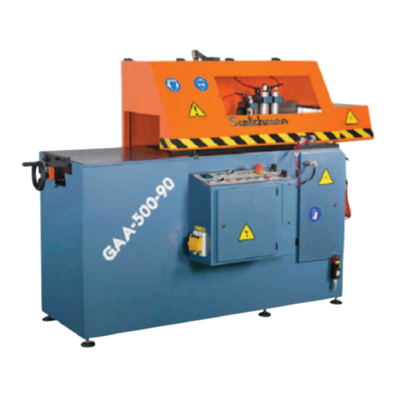
- Page 1 WWW.SCOTCHMAN.COM MODEL GAA-500-90 NF AUTO UPCUT COLD SAW PRINTED OCTOBER 2020 Page 1...
-
Page 2: Table Of Contents
TABLE OF CONTENTS 1.0 INTRODUCTION 1.1 Legislation applicable to the planning and construction of the machine. 1.2 Warranty 2.0 GENERAL MACHINE DATA 2.1 Machine identification data. 2.2 Technical data. 2.3 Electrical data. 2.4 Noise level. 2.5 Base cabinet. 3.0 INDICATIONS REGARDING TRANSPORT AND STORAGE 4.0 INSTRUCTIONS FOR ANCHORING AND SERVICE START-UP 4.1 Anchoring instructions. -
Page 3: Legislation Applicable To The Planning And Construction Of The Machine
2004/108/CEE On "Electromagnetic Compatibility". 1.2 WARRANTY Scotchman Industries, Inc. will, within 2 years of date of purchase, replace F.O.B. the factory or refund the purchase price for any goods which are defective in materials or workmanship and, at the seller’s option, returns the defective goods, freight and delivery prepaid, to the seller, which shall be the buyer’s sole and exclusive remedy for defective goods. -
Page 4: General Machine Data
2.0 GENERAL INFORMATION 2.1 MACHINE IDENTIFICATION DATA Model: GAA - 500 - 90° Serial number: Manufacturing year: NOTE: In order to request spare parts, whether covered by the warranty or not, always indicate the model and serial number of the machine; as well as the name of the part and the code that appears in the last chapter of the parts exploded views. -
Page 5: Electrical Data
2.3 ELECTRICAL DATA Power supply Motor power Total consumption 220 V Three phase 3 kW/7-1/2 HP 24 A 460 V Three phase 3 kW/7-1/2 HP 12 A 2.4 NOISE LEVEL At a distance of 60cm RUNNING OFF-LOAD 68 Db (A) Leq MACHINING A 70 X 50 PROFILE 108 Db (A) Leq ATTENTION: When working with the machine, use individual hearing protection equipment. -
Page 6: Indications Regarding Transport And Storage
3.0 INDICATIONS REGARDING TRANSPORT/STORAGE The machine is delivered on a pallet in order to be transported by forklift. Store in the vertical position. Do not stack. If the machine remains stored for a long period of time, periodically lubricate it. Do not expose to the elements. -
Page 7: Blade Installation
4.3 BLADE INSTALLATION This machine uses a 500mm blade with a 50mm arbor. Set the saw to ninety degrees and disconnect the power. Open the cabinet door and remove the existing blade. NOTE: The blade nut is right hand threaded. Insert the rod provided with the machine into the blade flange (5) and loosen the blade nut (6) with the wrench provided. -
Page 8: Instructions For Use
5.0 INSTRUCTIONS FOR USE 5.1 PROPER AND IMPROPER USE This is an automatic cut-off machine, especially designed for cutting aluminum profiles. The use of the machine for cutting other materials is hereby prohibited. Such use may cause damage to the machine and put the health and safety of the worker at risk. - Page 9 Page 9...
-
Page 10: Operating Controls
5.3 OPERATING CONTROLS This is the parts counter. This must have a value on it in order for the machine to run in the automatic mode. This button starts the automatic operation. Button J starts the saw motor. This is the hood open switch. This is the hood open indicator light. - Page 11 FIGURE 1 Page 11...
- Page 12 Piece counter with pre-selection. Feeder start. (Illuminated when on.) Lift protective shield. Protective shield lifted. Emergency. Power supplied to the machine. Emergency button with interlock. It stops the machine completely; thereby, keeping the material tight in the hold-down clamps. Feeder speed regulator. Blade raise advance.
- Page 13 THIS PAGE LEFT BLANK INTENTIONALLY. Page 13...
-
Page 14: Machine Operation
5.4 MACHINE OPERATION TO SET THE MACHINE UP FOR AN OPERATION: Open the hood and place your material in the machine, with 3/8" to 1/2" extending beyond the cut slot for the blade. Set the vise so it is within 1/4 of an inch of the material and clamp the shuttle vise. If the shuttle vise is not properly clamped, the red Material Out light on the vise will be on. - Page 15 FIGURE 2 FIGURE 3 Page 15...
- Page 16 FIGURE 5 Page 16...
- Page 17 FIGURE 6 Page 17...
-
Page 18: General Rules And Safety Checks
5.5 GENERAL RULES & SAFETY CHECKS Before using the machine, check the efficiency and perfect operation of all safety devices and check that the moving parts of the machine are not blocked, that there are no damaged parts and that all machine components are positioned and work correctly. -
Page 19: Qualified Personnel For Maintenance And Repair Work
6.2 QUALIFIED PERSONNEL FOR MAINTENANCE All repairs shall be made exclusively by qualified personnel, thereby always using original replacement parts. If not, the machine may be damaged or the user may be injured. The maintenance and cleaning of the machine must not be neglected. The life of the machine and its optimal operation depend on it considerably. -
Page 20: Manufacturer Recommendations
6.4 MANUFACTURER RECOMMENDATIONS In the event that the machine is broken down or the saw blades must be replaced, place a padlock on the protection switch and place the keys under the care of qualified personnel. Before working on any electrical devises, disconnect the plug from the power supply. If extension cords are used, ensure that the cable has the appropriate cross-section for the power of the machine. -
Page 21: Drawings And Schematics
7.0 DRAWINGS & SCHEMATICS CH 00 COUNTER 03 04 05 06 1 CH 0 CH 100-240V OMROM 100 - 240 V 11 CH 10 CH 24 VDC 02 03 COUNTER 1 AUTO SHIELD INDICATOR VOLTAGE INDICATOR GREEN INDICATOR YELLOW GREEN EMERGENCY BLADE RAISE... - Page 22 POWER CIRCUIT FIGURE 8 Page 22...
- Page 23 FIGURE 9 Page 23...
- Page 24 RIGHT SIDE CLAMP Also - See Fig. 6 Page 17 LEFT SIDE CLAMP DESIGNATION CODE NO. DESIGNATION CODE WORKING PLATE 2059000064 POLY V 1016J BELT* 1283* ROKER SUPPORT 2050000322 TURRET 2059000024 ROKER 2050000332 LEFT TURRET PLATE ROKER ROTATION SHAFT 2040000072 RIGHT TURRET PLATE WASHER M-12 TD12500012...
-
Page 25: Electrical Components And Wire Numbers
8.0 ELECTRICAL COMPONENTS & WIRE NUMBERS ITEM PART # DESCRIPTION Digital Pulse Counter E000000072 Feeder start E000000071 Lift protective shield selector E000NVAC30 Protective shield lifted E000RVAC30 Emergency indicator E000VVAC30 Power supplied to the machine E0000E0082 Emergency button with interlock N000000018 Feeder speed regulator Blade raise advance E000000075... - Page 27 Page 27...
-
Page 28: Valve Bank
10.0 VALVE BANK ITEM PART # DESCRIPTION N000000A34 Electrov. 5/2 1/8" MONO N000000A34 Electrov. 5/2 1/8" MONO N000000A34 Electrov. 5/2 1/8" MONO N000000A34 Electrov. 5/2 1/8" MONO Q5-6 N00000AB34 Electrov. 5/2 1/8" BI N000000S14 Silencer 1/4" 1/4" ∅8 L fitting N000CC1408 1/8"... - Page 29 THIS PAGE LEFT BLANK INTENTIONALLY. Page 29...
-
Page 30: Main Frame Assembly
11.0 MAIN FRAME ASSEMBLY ITEM PART # DESCRIPTION 2059000064 Working plate 2050000322 Roker support 2050000322 Roker 2040000072 Rocker rotation shaft TD12500012 M-12 washer TD91212025 DIN 912 M-12 x 25 PIN 2059007522 7.5 HP III phase motor 2169000142 Motor pulley J16 TD93110050 DIN 931 M-10 x 50 PIN 2050000092... -
Page 32: Shuttle Feed System
12.0 SHUTTLE FEED SYSTEM Page 32... - Page 33 Page 33...
-
Page 34: Optional Chip Collector - Wire Locations
BLUE Wire - goes to 0 Jumper Wire - goes to #2 Incoming Wires from Chip Collector DATE: SCALE: PART NAME: TOLERANCE (UNLESS SPECIFIED) Scotchman Inds. Scotchman Inds. Chip Collector 12/10/19 .0 = +/-.02 (.5mm) None .00 = +/-.01 (.25mm) GAA-500 &...
Need help?
Do you have a question about the GAA-500-90 NF and is the answer not in the manual?
Questions and answers